mail control valve


Valve điều khiển áp suất: Pressure control valve
Ngày tải lên :
08/01/2014, 01:45
... đồng đều.
Valve này chia làm ba phần:
1- Phần thân vỏ valve với lõi con trượt (tương đối giống như valve phân phối thông thường).
Dưới đây là hình ảnh so sánh sự khác nhau của lõi valve điện ... chế ở một số
chức năng nhất định.
hydraulics.vn
Van nút (Plug Valve)
- 12
- 1.7K
- 18
Control valves tuning
Ngày tải lên :
12/03/2014, 16:34
... TUNING
Page 1 of 13
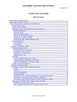
Control Valves and Tuning
Table of Contents
Control Valves AND TUNING 1
Control Valves AND TUNING 2
RELATIONSHIP OF MAJOR COMPONENTS 2
Control Valve Bodies 2
Control - Valve Actuators ... INTERACTING CONTROL LOOPS 11
DEFAULT CONTROLLER TUNING PARAMETERS 11
CONTROL LOOP SCAN RATES 12
PID ALGORITHM DEFAULT TUNING CONSTANTS 13
Berry’s Commissioning Handbook
CONTROL VALVES AND ... Handbook
CONTROL VALVES AND TUNING
Page 2 of 13
CONTROL VALVES AND TUNING
Selecting the proper control valve for each application involves many factors. The valve body
design, actuator, style, and...
- 13
- 695
- 0
control valves hanbook
Ngày tải lên :
14/03/2014, 19:43
... final control element
must implement the strategy selected
by the controller.
The most common final control ele-
ment in the process control industries
is the control valve. The control valve
manipulates ... point.
Many people who talk about control
valves or valves are really referring to
a control valve assembly. The control
valve assembly typically consists of
the valve body, the internal trim parts,
an ... butterfly valve
compared to a line-size globe valve.
The globe valve has a much wider
control range than the butterfly valve.
Other valve styles, such as V-notch
ball valves and eccentric plug valves
generally...
- 295
- 463
- 1

CONTROL VALVE HANDBOOK Fourth Edition ppt
Ngày tải lên :
29/03/2014, 08:20
... 0.46
Valve B
VALVE ACTION / OPENING 2 5.61 7.74
VALVE ACTION / CLOSING −2 0.46 1.67
VALVE ACTION / OPENING 5 1.14 2.31
VALVE ACTION / CLOSING −5 1.04 2
VALVE ACTION / OPENING 10 0.42 1.14
VALVE ... 1.14
Valve C
VALVE ACTION / OPENING 2 4.4 5.49
VALVE ACTION / CLOSING −2 NR NR
VALVE ACTION / OPENING 5 5.58 7.06
VALVE ACTION / CLOSING −5 2.16 3.9
VALVE ACTION / OPENING 10 0.69 1.63
VALVE ... a control valve for
present conditions and then replace
the valve when conditions change.
When selecting a valve, it is important
to consider the valve style, inherent
characteristic, and valve...
- 297
- 746
- 0

Fisher ® Pulp and Paper Solutions Reliable control valve technologies for on-specification product. pptx
Ngày tải lên :
01/04/2014, 00:20
...
through control valves, but it may also cause material damage,
excessive noise, and high vibration. This material damage can
severely affect the control valve s operability and overall control ... envelope package size for tight spaces.
Fisher V150 Vee-Ball
™
control valve, FieldQ
™
actuator, and FIELDVUE DVC2000 digital valve controller
Fisher
®
Pulp and Paper Solutions | 27
In the power ... following literature:
http://www.YouTube.com/user/FisherControlValve
http://www.Twitter.com/FisherValves
http://www.Facebook.com/FisherValves
http://www.LinkedIn.com/groups/Fisher-3941826
“Fisher
®
...
- 32
- 449
- 0
IEC 60534 6 1 industrial process control valves mounting details for attachment of positioners
Ngày tải lên :
04/04/2014, 11:29
... ``````-`-`,,`,,`,`,,`
60534-6-1 © IEC:1997 – 7 –
INDUSTRIAL-PROCESS CONTROL VALVES –
Part 6: Mounting details for attachment of positioners to control valves –
Section 1: Positioner mounting on linear actuators
1 ... positionneurs
sur les actionneurs linéaires
Industrial-process control valves –
Part 6:
Mounting details for attachment of
positioners to control valves –
Section 1: Positioner mounting on
linear actuators
... positionneurs
sur les actionneurs linéaires
Industrial-process control valves –
Part 6:
Mounting details for attachment of
positioners to control valves –
Section 1: Positioner mounting on
linear actuators
Numéro...
- 40
- 627
- 0
IEC 60534 6 2 industrial process control valves mounting details for attachment of positioners
Ngày tải lên :
04/04/2014, 11:29
... ``````-`-`,,`,,`,`,,`
60534-6-2 © IEC:2000 – 5 –
INDUSTRIAL-PROCESS CONTROL VALVES –
Part 6-2: Mounting details for attachment of positioners
to control valves – Positioner mounting on rotary actuators
1 Scope
This ... proportional to the control valve travel.
b) This standard also covers the direct connection between the positioner feedback and the
shaft (or its axial extension) of a rotary control valve. In such ... ELECTROTECHNICAL COMMISSION
––––––––––––
INDUSTRIAL-PROCESS CONTROL VALVES –
Part 6-2: Mounting details for attachment of positioners
to control valves – Positioner mounting on rotary actuators
FOREWORD
1)...
- 20
- 419
- 0
IEC 60534 7 industrial process control valves data sheet
Ngày tải lên :
04/04/2014, 11:30
... Handling Services
534-7
O
IEC -7-
INDUSTRIALPROCESS CONTROL VALVES
Part
7:
Control valve data sheet
1. Introduction
The writing of control valve specifications is an extremely important segment ...
tioners to control valve actuators.
Part 7: Control valve data sheet.
Part 8: Noise considerations. Section One
-
Lab-
oratory measurement of noise generated by aero-
dynamic flow through control ...
dimensions for flanged, two-way, globe-type
control valves.
Section Two
-
Face-to-face dimensions for
flangeless control valves except water butterfly
valves.
Part 4: Inspection and routine...
- 38
- 584
- 0
IEC 60534 8 1 industrial process control valves noise considerations
Ngày tải lên :
04/04/2014, 11:31
... levels radiated by control valves and/or associated piping con-
figurations, including ked restrictions, through which compressible fluids are passing.
Note.
-
Control
valves discharging ... régulation
Industrial-process control valves
Part
8:
Noise considerations
Section One
-
laboratory measurement
of
noise generated
by aerodynamic
flow
through control valves
O
CE1
1986
Droits ... test travel
14) Pressure differential ratio factor of a control valve without attached
15) Pressure differential ratio factor of a control valve with attached fittings,
16) Piping geometry factor,...
- 21
- 392
- 0
IEC 60534 8 2 industrial process control valves noise considerations
Ngày tải lên :
04/04/2014, 11:32
...
:
1987,
Industrial-process control valves
-
Part
7:
Control valve terminology and
general considerations.
IEC 534-2-3: 1983,
Industrial-process control valves
-
Part
2:
Flow capaclw ... radiated from the control valve itself and the noise
generated by the valve
but
radiated from the associated piping system. The test data are
expressed as sound pressure levels of the valve under ... characteristic pressure ratio factor
xFz
of a control valve;
b) to predict valve noise for given process conditions;
c) to compare the performance of different valves;
d)
to plan measures for increasing...
- 37
- 464
- 1
IEC 60534 8 3 control valve aerodynamic noise prediction method
Ngày tải lên :
04/04/2014, 11:33
... 22
1
CE2
p
p
=
(6)
5.2 Regime definition
A control valve controls flow by converting potential (pressure) energy into turbulence. Noise in
a control valve results from the conversion of a small ... are not used in this standard.
Table 2 – Typical values of valve style modifier
F
d
(full size trim)
Relative flow coefficient
ΦΦ
Valve type Flow direction
0,10 0,20 0,40 0,60 0,80 1,00
Globe, ... 1
12
L
2
=−
−
(1)
NOTE 1 This equation is the definition of
F
L
for subsonic conditions.
NOTE 2 When the valve has attached fittings, replace
F
L
with
F
LP
/
F
p
.
NOTE 3 The factor
F
L
is needed...
- 122
- 525
- 0


- mail server
- electronic control systems
- electronics control system – monitors recap
- auto lighting control system
- bcm (body control module)
- emission control system
- intake restriction control
- outline of injection timing control
- pneumatic valves for precision and control
Tìm thêm:
- hệ việt nam nhật bản và sức hấp dẫn của tiếng nhật tại việt nam
- xác định các mục tiêu của chương trình
- xác định các nguyên tắc biên soạn
- khảo sát các chuẩn giảng dạy tiếng nhật từ góc độ lí thuyết và thực tiễn
- khảo sát chương trình đào tạo của các đơn vị đào tạo tại nhật bản
- khảo sát chương trình đào tạo gắn với các giáo trình cụ thể
- xác định thời lượng học về mặt lí thuyết và thực tế
- tiến hành xây dựng chương trình đào tạo dành cho đối tượng không chuyên ngữ tại việt nam
- điều tra đối với đối tượng giảng viên và đối tượng quản lí
- điều tra với đối tượng sinh viên học tiếng nhật không chuyên ngữ1
- khảo sát thực tế giảng dạy tiếng nhật không chuyên ngữ tại việt nam
- khảo sát các chương trình đào tạo theo những bộ giáo trình tiêu biểu
- nội dung cụ thể cho từng kĩ năng ở từng cấp độ
- xác định mức độ đáp ứng về văn hoá và chuyên môn trong ct
- phát huy những thành tựu công nghệ mới nhất được áp dụng vào công tác dạy và học ngoại ngữ
- mở máy động cơ lồng sóc
- mở máy động cơ rôto dây quấn
- các đặc tính của động cơ điện không đồng bộ
- hệ số công suất cosp fi p2
- đặc tuyến hiệu suất h fi p2