orthogonal frequency division multiplexing for wireless communications 1st edition by li stuber


Theory of stochastic local area channel modeling for wireless communications
Ngày tải lên :
20/11/2012, 11:36
... spatial relationships as well.
Space -Frequency Transform Map
For a static channel, we may extend the time -frequency transform map in Figure 2.9 for the
space -frequency relationships shown in Figure ... SpecificAnalyticalProblems 186
8.1.3 ApplicationstoWirelessTechnology 187
vii
THEORY OF STOCHASTIC LOCAL AREA CHANNEL
MODELING FOR WIRELESS COMMUNICATIONS
by
Gregory D. Durgin
Final Dissertation ... definitions.
|h( )|f
~
frequency, f
f
c
B
c
Frequency Selectivity
V
0
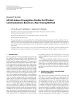
Figure 2.6: Example of a frequency- varying channel.
The loss of frequency coherence in a wireless communications system is caused by the
dispersion...
- 207
- 369
- 0

Tài liệu Rf Mems Circuit Design For Wireless Communications pptx
Ngày tải lên :
19/01/2014, 20:20
... Circuit Design for Wireless Communications
2
Elements of RF Circuit Design
2.1 Introduction
The design of RF MEMS circuits for wireless applications is predicated upon
the well-established principles ... Design for Wireless Communications
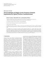
86%
11%
3%
2000
81%
15%
4%
2001
75%
20%
5%
2002
70%
25%
5%
2003
Phone line Power line Wireless
Figure 1.4 Distribution of interconnection media usage for home ... (3) the space platform.
4 RF MEMS Circuit Design for Wireless Communications
Information
Voice
Broadband data
Messaging
Navigation
DBS
Internet
Video
Wireless appliances
?
Power/Bandwidth...
- 280
- 545
- 0

Channel Equalization for Wireless Communications: From Concepts to Detailed Mathematics doc
Ngày tải lên :
16/03/2014, 22:20
... scenarios
for which reliable communications is desirable. In the literature, channel modeling
information can be found for
ã wireless (radio) communications [Tur72, Suz77],
ã wireline communications ... extended by considering several multiplicities. The trans-
mitter multiplexes multiple symbols in parallel, such as code -division multiplexing
(CDM) and orthogonal frequency- division multiplexing ... waveform is the same
for each symbol period m.
LIST OF FIGURES XVII
6.4 Traveling salesperson problem. 120
6.5 Traveling salesperson tree search. 121
6.6 Traveling salesperson trellis....
- 244
- 860
- 0

Tdd - cdma for wireless communications
Ngày tải lên :
27/05/2014, 04:01
... of ±1 with
equal probability,
ω=2πf is the carrier frequency, and J =
−1
. The
Mobile Radio Communications 25
28 TDD-CDMA for Wireless Communications
f
0
f
3
f
2
f
1
Frequency
Time
One bit period
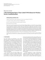
One ... station
Mobile terminal
(TDD)
Base station
Mobile terminal
Common uplink and downlink frequency band
Uplink frequency band
Downlink frequency band
Figure 1.4 TDD and FDD.
TEAMFLY
... TDD-CDMA for Wireless Communications
Riaz Esmailzadeh
Masao Nakagawa
Artech House
Boston ã London
www.artechhouse.com
1.1 Mobile Communications
The mobile communications revolution took place for...
- 191
- 310
- 0
Báo cáo hóa học: " An orthogonal spectrum sharing scheme for wireless sensor networks" potx
Ngày tải lên :
21/06/2014, 03:20
... above propo sed
scheme, henceforth call ed as orthogonal spectrum shar-
ing scheme (OSSS), by deriving the closed-form expres-
sions for average SNR of the primary system. For
comparison, we also ... all the radio links between PT, PR, ST
and SR can be characterized by their respective posi-
tions on the straight line.
Figure 5 shows the average SNR performance of
primary system for OSSS,
SNR
p
with ... f
between the performance of primary and secondary sys-
tems, and the performance of one system is limited by the
interference from the other system. As we increase the
value of a, the performance of...
- 11
- 332
- 0


Báo cáo hóa học: " Research Article Novel Techniques of Single-Carrier Frequency-Domain Equalization for Optical Wireless Communications" doc
Ngày tải lên :
21/06/2014, 08:20
... frequency domain equalization (SCFDE) over a diffuse optical wireless (DOW)
communications. Recently orthogonal frequency division multiplexing (OFDM) has been applied to DOW communications.
However, ... performance of OFDM can severely be affected by the nonlinear
characteristics of light emitting diodes (LED). To avoid a PAPR problem, we present in this paper a modified form of SCFDE for
DOW communications. ... for use in
indoor wireless data transmission [1, 2]. Diffuse optical
wireless (DOW) communications offer a viable alternative
to radio frequency (RF) communication for indoor use and
other applications...
- 13
- 367
- 0

Báo cáo sinh học: "MAC and baseband processors for RF-MIMO WLAN EURASIP Journal on Wireless Communications and " doc
Ngày tải lên :
18/06/2014, 22:20
... link quality, allowing for higher physical data rates, the loss due to RTS/CTS
overhead is overcompensated for frame sizes above 100 bytes (at 6 Mbit/s). The loss can be
further minimized by ... distributed freely for any purposes (see copyright notice below).
For information about publishing your research in EURASIP WCN go to
http://jwcn.eurasipjournals.com/authors/instructions/
For information ... is limited in the maximum achievable
resolution because of noise processes, process variations or nonlinear behaviour of the devices.
Therefore, the signal processing has to be calibrated by...
- 38
- 424
- 0
Emerging Communications for Wireless Sensor Networks Part 1 pptx
Ngày tải lên :
20/06/2014, 06:20
...
Therefore, wireless link modules” are the building blocks for individual wireless
nodes, so as to establish different types of abstract wireless links. For example,
categories of wireless links ...
Therefore, wireless link modules” are the building blocks for individual wireless
nodes, so as to establish different types of abstract wireless links. For example,
categories of wireless links ... of the wireless link layer and
link QoS.
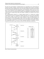
Fig. 3. State Diagram of the Wireless Link Layer
A state diagram of the wireless link layer can be illustrated in Figure 3. The wireless
link...
- 20
- 467
- 0
Emerging Communications for Wireless Sensor Networks Part 2 ppt
Ngày tải lên :
20/06/2014, 06:20
... comparison study of
the uplink performance of W-CDMA and OFDM for mobile multimedia
communications via LEO satellites. Personal Communications, IEEE [see also IEEE
Wireless Communications] , 8(3), ... 1. Travelling times along pipes for different sensors
Emerging Communications for Wireless Sensor Networks20
4. Physical Layer Configuration and Simulation
Reliable communication links are ...
Antennas for Cellular Coverage from a High Altitude Platform. IEEE Transactions
on Wireless Communications, 2, No. 3, 484-492.
Tozer, T. C., & Grace, D. (2001). High-Altitude Platforms for Wireless...
- 20
- 330
- 0
Emerging Communications for Wireless Sensor Networks Part 3 pdf
Ngày tải lên :
20/06/2014, 06:20
... backbone of our platform or Tool-Chain. For the modelling a graphical
editor, based on the Eclipse Modelling Framework and the Graphical Modelling Framework
(GMF), was developed. For the examination ...
frameworks are Eclipse platform open source projects.
Furthermore the emphasis lies on the integration of essential functionalities, which regard
the administration and Management of the Wireless Sensor ... important character of the platform. The realisation of such
combinations was achieved by the plug-in oriented architecture in accordance with the
Eclipse platform. On the one hand the user...
- 20
- 363
- 0
Tìm thêm:
- hệ việt nam nhật bản và sức hấp dẫn của tiếng nhật tại việt nam
- xác định các mục tiêu của chương trình
- xác định các nguyên tắc biên soạn
- khảo sát các chuẩn giảng dạy tiếng nhật từ góc độ lí thuyết và thực tiễn
- khảo sát chương trình đào tạo của các đơn vị đào tạo tại nhật bản
- khảo sát chương trình đào tạo gắn với các giáo trình cụ thể
- xác định thời lượng học về mặt lí thuyết và thực tế
- tiến hành xây dựng chương trình đào tạo dành cho đối tượng không chuyên ngữ tại việt nam
- điều tra đối với đối tượng giảng viên và đối tượng quản lí
- điều tra với đối tượng sinh viên học tiếng nhật không chuyên ngữ1
- khảo sát thực tế giảng dạy tiếng nhật không chuyên ngữ tại việt nam
- khảo sát các chương trình đào tạo theo những bộ giáo trình tiêu biểu
- nội dung cụ thể cho từng kĩ năng ở từng cấp độ
- xác định mức độ đáp ứng về văn hoá và chuyên môn trong ct
- phát huy những thành tựu công nghệ mới nhất được áp dụng vào công tác dạy và học ngoại ngữ
- mở máy động cơ lồng sóc
- mở máy động cơ rôto dây quấn
- các đặc tính của động cơ điện không đồng bộ
- hệ số công suất cosp fi p2
- đặc tuyến hiệu suất h fi p2