mạch logic kỹ thuật số
Logic kỹ thuật số thử nghiệm và mô phỏng P2
... ignores delay values within a logic element; it simply calculates the logic function performed by the element. A nominal-delay simulator assigns delay values to logic elements based on manufacturer’s ... of logic, is the set of elements encoun- tered during a backtrace from an internal circuit node, called the apex, to input state points. Definition 2.3 A predecessor of a logic element is a logic ... ranges of signals. First consider the strengths. A logic 1 or 0 can be represented as strong, weak, or floating. The strong value is gen- erated by a logic device that is driving an output. For example,...
Ngày tải lên: 17/10/2013, 22:15
Logic kỹ thuật số thử nghiệm và mô phỏng P3
... follows, the positive logic convention will be used. Any voltage between ground (Gnd) and +0.8 V represents a logic 0. A voltage between +2.4 V and +5.0 V (Vcc) represents a logic 1. A voltage between ... is arbitrarily selected and required to generate a logic 1, then the upper AND gate must generate a logic 1, requiring that inputs X 1 and X 2 must both be at logic 1. As before, a known value must be ... addition to correct logic response, it will usually be necessary to verify that the design performs within required time constraints. 3.2 APPROACHES TO TESTING Testing digital logic consists of...
Ngày tải lên: 20/10/2013, 17:15
Logic kỹ thuật số thử nghiệm và mô phỏng P4
... is an AND gate, and a logic 1 on its output only occurs if all its inputs have logic 1 values. This is called implication ; a 1 on the output of an AND gate implies logic 1 on all its inputs. ... greater difficulties because a logic assignment at its upper input must be justified through other logic, and a test at its output must be propagated through additional logic. An arbitrary propagation ... n 1 (A), assign a 1 to the fanout point, otherwise assign a 0. Logic values assigned during backtrace depend on (a) the function of the logic gate through which the backtrace passes and (b) the value...
Ngày tải lên: 20/10/2013, 17:15

Logic kỹ thuật số thử nghiệm và mô phỏng P5
... 254 SEQUENTIAL LOGIC TEST develop D-cubes for the super logic blocks by extending the basic memory element D-cubes through the preceding combinational logic. In the second step, beginning with a super logic ... super logic blocks. 2. Trace super logic block D-cubes to define sequential D-chains that define sequential circuit propagation paths. 3. Determine an exercise sequence for each sequential logic ... SRCC⁄⋅⋅+= CC⁄ 238 SEQUENTIAL LOGIC TEST component. Unfortunately, this assumption, while convenient, is an oversimplifica- tion. An error may indeed be a result of one or more logic faults, but it may...
Ngày tải lên: 24/10/2013, 15:15
Logic kỹ thuật số thử nghiệm và mô phỏng P6
... AUTOMATIC TEST EQUIPMENT Pin data PD 1 and PD 2 are identical; a logic 1 in pin memory is followed by a logic 0, another 1, and then a 0. However, because the timing generators are ... if all of them fail in an identical fashion, then the logical assumption is that there is a design error that occurred during either the logic design process or the physical design process. REFERENCES 321 6.2 ... In-Circuit and Functional, Electron. Eng. Times, January 3, 1983, pp. 25–29 21. Miczo, A., Digital Logic Testing and Simulation, Chapter 6, John Wiley & Sons, New York, 1986. 22. Runyan, S.,...
Ngày tải lên: 24/10/2013, 15:15
Logic kỹ thuật số thử nghiệm và mô phỏng P7
... of vectors, see Section 7.9.5. 7.8.3 Behavioral Fault Simulation The advent of RTL logic design and the resulting reliance on logic synthesis has had a major impact on design styles and productivity. ... No general method exists for spotting redundancies in logic circuits. 7.5.4 Bridging Faults Faults can be caused by shorts or opens. In TTL logic, an open at an input to an AND gate prevents that ... Figure 2.8. The signal 1’b1 connected to the preset in the dff denotes a logic 1. Similarly, 1’b0 denotes a logic 0. The next element in ckt7p3 is called bufif1 . The bufif1 ...
Ngày tải lên: 28/10/2013, 22:15
Logic kỹ thuật số thử nghiệm và mô phỏng P8
... shadow logic between scan registers and memory. 19 This is combinational logic that can not be directly accessed by the scan circuits. If the shadow logic consists solely of addressing logic, ... with IEEE1149.1 boundary scan. TDI TDO T A P TMS TCK TAP TAP TAP TAP TMS TCK Core logic Core logic Core logic Core logic ... the output of the AND gate fans out to other logic, that one gate affects observability of logic up to that point and it affects controllability of logic following that node. (a) (b) QD Q Delay THE...
Ngày tải lên: 28/10/2013, 22:15

Logic kỹ thuật số thử nghiệm và mô phỏng P9
... test the oper- ational logic. Examples of first-degree hardcore include such things as a ROM dedicated to test which is loaded via a special access path not used by operational logic, a dedicated ... Mode SRL + SRL Data Scan-in Scan-out Scan-out (a) (b) + + Scan-in MISR PRG SI 1 SI 2 SI 3 SI n SO 1 SO 2 SO 3 SO N Comb. logic Comb. logic 488 BUILT-IN SELF-TEST Figure 9.21 Desktop Management Interface (DMI). Some of the information ... complex logic operations on the LFSR bits can provide other ratios. When backtracing from two or more outputs, there is a possibility that an input may have to be biased so as to favor a logic...
Ngày tải lên: 07/11/2013, 20:15

Logic kỹ thuật số thử nghiệm và mô phỏng P10
... 45% random logic. Assume that in shipped parts, memory has 2 DPM (defects per million) and that the logic has 1100 DPM. What is the overall DPM for the chip? If process yield for the logic is 70%, ... array faults, and read/write logic faults. From there we use the fact, demonstrated by Nair, Thatte, and Abraham, 7 that faults in memory addressing and read/write logic, which includes sense ... coupling fault between cells. If no cell is addressed, then, depending on the logic, the response from the read logic may appear as a stuck-at-1 or a stuck-at-0. If the wrong cell is addressed,...
Ngày tải lên: 07/11/2013, 20:15

Logic kỹ thuật số thử nghiệm và mô phỏng P11
... paths to ground or power. On average, a node is going to be at logic 0 half the time and at logic 1 half the time. If the node is at logic 0 and is connected to a pullup, a path exists for current ... pulldowns. No floating nodes. No logic contention. If analog circuits appear in the design, they should be on separate power supplies. No unconnected inputs on unused logic. The purpose of these design ... behavioral model for very low level behavioral devices, namely, the logic gates. Faults such as high-resistance bridging shorts, inside a logic gate or between con- nections to adjacent gates, may not...
Ngày tải lên: 07/11/2013, 20:15

Toán logic & kỹ thuật số bản chất của các hệ thống số hiện đại và sự liên hệ hữu cơ giữa toán logic với kỹ thuật số
Ngày tải lên: 06/12/2013, 17:28

Tài liệu Logic kỹ thuật số thử nghiệm và mô phỏng P12 docx
... able to recog- nize whether a fault effect currently being processed is in control logic or data-flow logic. Control logic includes such things as status registers and mode control regis- ters. For ... code coverage is to verify that the input vectors established logic values on internal signals in such a way that the outcome of a logic transaction depends only on one particular signal, namely, ... may be trapped in control logic. If it is trapped in a data path, then the object is to propa- gate it forward toward an output. If the fault is trapped in control logic, then it can usually...
Ngày tải lên: 15/12/2013, 04:15


kỹ thuật số sử dụng các mạch vi điện tử lôgic mức độ tổng hợp nhỏ và vừa (SSI, MSI)
Ngày tải lên: 06/12/2013, 17:35
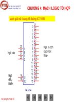
Tài liệu Kỹ thuật điện tử - Kỹ thuật số - Mạch logic tổng hợp (phần 3) docx
... $ $ = = $ $ $ $ = CHƯƠNG 4: MẠCH LOGIC TỔ HỢP CHƯƠNG 4: MẠCH LOGIC TỔ HỢP Mạch so sánh hai số NP 8 bit dùng IC 7485 D ... khi truyền. MẠCH TẠO VÀ KIỂM TRA BIT CHẲN LẼ CHƯƠNG 4: MẠCH LOGIC TỔ HỢP MẠCH SO SÁNH Mạch so sánh hai số nhị phân ... 1 0 1 0 1 1 1 1 1 Cộng hai số nhị phân có nhớ CHƯƠNG 4: MẠCH LOGIC TỔ HỢP CHƯƠNG 4: MẠCH LOGIC TỔ HỢP BABA ⊕== )( BABA...
Ngày tải lên: 13/12/2013, 12:15

Tài liệu Kỹ thuật điện tử - Kỹ thuật số -Mạch logic tổ hợp - Mạch mã hóa (phần1) pptx
... Thuật Điện Tử II Bài giảng Kỹ Thuật Số CHƯƠNG 4: MẠCH LOGIC TỔ HỢP MẠCH MÃ HOÁ MẠCH GIẢI MÃ MÃCH GHÉP KÊNH MẠCH PHÂN KÊNH MẠCH SỐ HỌC MẠCH TẠO BIT KIỂM TRA CHẲN LẼ ALU Học viện công ... MẠCH LOGIC TỔ HỢP Khi G=1,BA=00: Các ngõ ra khác đều bằng 1 Học viện công nghệ BCVT Khoa Kỹ Thuật Điện Tử II Bài giảng Kỹ Thuật Số CHƯƠNG 4: MẠCH LOGIC TỔ HỢP Bảng hoạt động Mạch ... 4: MẠCH LOGIC TỔ HỢP Khi G=0,BA=01, ngõ ra Y 1 =0 Các ngõ ra khác đều bằng 1 Học viện công nghệ BCVT Khoa Kỹ Thuật Điện Tử II Bài giảng Kỹ Thuật Số CHƯƠNG 4: MẠCH LOGIC TỔ HỢP Mạch...
Ngày tải lên: 23/12/2013, 06:16

Tài liệu Kỹ thuật điện tử - Kỹ thuật số - Mạch logic tổng hợp - Mạch giải mã kéo led 7 đoạn (phần2) pptx
... ! FGH G 2 & ' 3 ! CHƯƠNG 4: MẠCH LOGIC TỔ HỢP MẠCH GIẢI MÃ KÉO LED 7 ĐOẠN CHƯƠNG 4: MẠCH LOGIC TỔ HỢP MẠCH GIẢI MÃ KÉO LED ... "@@" A B * " @ C D *D *B ** *) E *C *@ ! FGH G 2 & ' 3 ! CHƯƠNG 4: MẠCH LOGIC TỔ HỢP MẠCH GIẢI MÃ KÉO LED 7 ĐOẠN "@@" A B * " @ C D *D *B ** *) E *C *@ ... "@@" A B * " @ C D *D *B ** *) E *C *@ ! FGH G 2 & ' 3 ! CHƯƠNG 4: MẠCH LOGIC TỔ HỢP MẠCH GIẢI MÃ KÉO LED 7 ĐOẠN "@@" A B * " @ C D *D *B ** *) E *C *@ ...
Ngày tải lên: 23/12/2013, 06:16

Tài liệu Kỹ thuật điện tử - Kỹ thuật số -Mạch logic thuần tự (phần1) pdf
... lại) CHƯƠNG 5: MẠCH LOGIC TUẦN TỰ MẠCH CHỐT CỔNG NAND Q Học viện công nghệ BCVT Khoa Kỹ Thuật Điện Tử II Bài giảng Kỹ Thuật Số CHƯƠNG 5: MẠCH LOGIC TUẦN TỰ MẠCH ĐẾM MẠCH ĐẾM ĐỒNG BỘ ... II Bài giảng Kỹ Thuật Số CHƯƠNG 5: MẠCH LOGIC TUẦN TỰ KHÁI NIỆM CHUNG • Mạch tuần tự là mạch logic có tính chất nhớ, có khâu trễ • Trạng thái tiếp theo của mạch phụ thuộc vào giá trị của kích ... xét: Mạch đếm từ 0 đến 5 (modulo =6) Bảng hoạt động Học viện công nghệ BCVT Khoa Kỹ Thuật Điện Tử II Bài giảng Kỹ Thuật Số CHƯƠNG 5: MẠCH LOGIC TUẦN TỰ MẠCH ĐẾM Đặc điểm mạch đếm...
Ngày tải lên: 23/12/2013, 06:16