electrical circuits 9th edition test
Electric Circuits, 9th Edition P82 potx
... RLC circuits, 280-285,473^75 resistor-capacitor (RC) circuits, 229-236,246 resistor-inductor (RL) circuits, 224-228,231-236,246 resistor-inductor-capacitor (RLC) circuits, 280-285 series RLC circuits, ... (RL) circuits, 212,214-220,224-228, 236-238,246 resistor-inductor-capacitor (RLC) circuits, 264-305, 473^175 second-order circuits, 264-305 sequential switching, 236-240,246 series RLC circuits, ... 217,475-476,506,662 unbounded, 240-241,246 RL circuits, see Resistor-inductor (RL) circuits RLC circuits, see Resistor-inductor-capacitor (RLC) circuits Root-mean-square (rms) value, 309-311,368-369,...
Ngày tải lên: 06/07/2014, 16:20

Electric Circuits, 9th Edition P1 ppt
... ds" F(«) rf/< , ; ,rff 0") - j"' -3 y \ ; rf,,_1/(0") 71-1 ^-V^ ELECTRIC CIRCUITS NINTH EDITION ELECTRIC CIRCUITS NINTH EDITION James W Nilsson Professor Emeritus Iowa State University Susan A ... Analysis 466 Introduction to Frequency Selective Circuits 522 Active Filter Circuits 558 Fourier Series 604 The Fourier Transform 644 Two-Port Circuits 678 The Solution of Linear Simultaneous ... 212 Natural and Step Responses of RLC Circuits 264 Sinusoidal Steady-State Analysis 306 Sinusoidal Steady-State Power Calculations 360 Balanced Three-Phase Circuits 398 Introduction to the Laplace...
Ngày tải lên: 06/07/2014, 16:20

Electric Circuits, 9th Edition P2 ppt
... Analyzing Cascaded Two-Port Circuits 696 Preface The ninth edition of Electric Circuits represents a planned revision designed to incrementally improve this introductory circuits text used by more ... practicing engineer WHY THIS EDITION? The ninth edition revision of Electric Circuits began with a thorough review of the text by instructors who currently use Electric Circuits and those who use ... Current-Divider Circuits 61 Voltage Division and Current Division 64 Measuring Voltage and Current 66 Measuring Resistance—The Wheatstone Bridge 69 Delta-to-Wye (Pi-to-Tee) Equivalent Circuits 71...
Ngày tải lên: 06/07/2014, 16:20
Electric Circuits, 9th Edition P3 pptx
... Emphasis The ninth edition continues to support the emphasis on the design of circuits in many ways First, many of the Practical Perspective discussions focus on the design aspects of the circuits The ... the pages of this text James W Nilsson Susan A Riedel ELECTRIC CIRCUITS NINTH EDITION •U \ Circuit Variables CHAPTER CONTENTS 1.1 Electrical Engineering: An Overview p 1.2 The International System ... represent the electrical source to the home The components labeled c, d, and e represent the wires that carry the electrical current from the source to the devices in the home requiring electrical...
Ngày tải lên: 06/07/2014, 16:20
Electric Circuits, 9th Edition P4 pdf
... for electrical systems is a circuit model The elements that comprise the circuit model are called ideal circuit components An ideal circuit component is a mathematical model of an actual electrical ... physical prototype can be constructed The physical prototype is an actual electrical system, constructed from actual electrical components Measurement techniques are used to determine the actual, ... iteration In this book, we use models that have been tested for between 20 and 100 years; you can assume that they are mature The ability to model actual electrical systems with ideal circuit elements...
Ngày tải lên: 06/07/2014, 16:20

Electric Circuits, 9th Edition P5 pot
... harm The electrical energy that can actually cause injury is due to electrical current and how it flows through the body Why, then, does the sign warn of high voltage? Because of the way electrical ... understanding of electrical engineering Before we can examine this aspect of electrical safety, we have to learn how voltages and currents are produced and the relationship between them The electrical ... analytical methods form the core of the electrical engineering techniques that will allow us to understand all electrical phenomena, including those relating to electrical safety At the end of this...
Ngày tải lên: 06/07/2014, 16:20
Electric Circuits, 9th Edition P6 doc
... important than its electrical properties for the flashlight design Electrically, we can model the connector with an ideal resistor, labeled R{ The case also serves both a mechanical and an electrical ... circuit Although this text emphasizes the skills required to solve circuits, you also will need other skills in the practice of electrical engineering, and one of the most important is modeling ... a dual role First, it provides an electrical conductive path between the dry cells and the case Second, it is Figure 2.9 • A flashlight can be viewed as an electrical system formed into a springy...
Ngày tải lên: 06/07/2014, 16:20
Electric Circuits, 9th Edition P7 ppsx
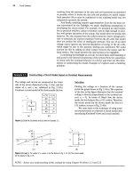
... need to use two more important algebraic relationships, known as Kirchhoff's laws, to solve most circuits We begin by redrawing the circuit as shown in Fig 2.15, with the switch in the ON state ... to the currents leaving the node gives /] — i() — = Figure 2.18 A The circuit for Example 2.8 b) Test the solution for i0 by verifying that the total power generated equals the total power dissipated...
Ngày tải lên: 06/07/2014, 16:20
Electric Circuits, 9th Edition P8 potx
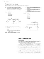
... Cooper, Electrical Safety Engineering, 2d ed (London: Butterworth, 1986); and C D Winburn, Practical Electrical Safety (Monticello, N.Y.: Marcel Dekker, 1988) Now we develop a simplified electrical ... from an analysis of accidents because, obviously, i t is not ethical to perform electrical experiments on people Good electrical design will limit current to a few milliamperes or less under all ... voltage difference exists between one arm and one leg of a human being Figure 2.25(b) shows an electrical model of the human body in Fig 2.25(a) The arms, legs, neck, and trunk (chest and abdomen)...
Ngày tải lên: 06/07/2014, 16:20
Electric Circuits, 9th Edition P9 pot
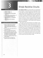
... Also try Chapter Problems 3.1-3.4 The Voltage-Divider and Current-Divider Circuits At times—especially in electronic circuits developing more than one voltage level from a single voltage supply ... circuit shown in Fig, 3.16 63 64 Simple Resistive Circuits ^ASSESSMENT PROBLEMS Objective 2—Know how to design simple voltage-divider and current-divider circuits 3.2 a) Find the no-load value of v0 ... Fig 3.5 with a single equivalent resistor < Combining resistors in parallel 60 Simple Resistive Circuits using conductance when dealing with resistors connected in parallel is more convenient...
Ngày tải lên: 06/07/2014, 16:20
Electric Circuits, 9th Edition P10 ppt
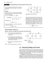
... 3.51 Answer: (a) 1500 ft; (b) yes 3.7 Delta-to-Wye (Pi-to-Tee) Equivalent Circuits 3.7 Delta-to-Wye (Pi-to-Tee) Equivalent Circuits The bridge configuration in Fig 3.26 introduces an interconnection ... interconnection because the A can be shaped into a TT without disturbing the electrical equivalence of the two configurations The electrical equivalence between the A and TT interconnections is apparent ... the Y structure can be shaped into a T structure without disturbing the electrical equivalence of the two structures The electrical equivalence of the Y and the T configurations is apparent from...
Ngày tải lên: 06/07/2014, 16:20
Electric Circuits, 9th Edition P11 ppt
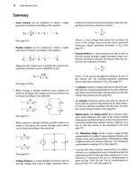
... of the circuits of Problem 3.1 3.1 For each of the circuits shown, a) identify the resistors connected in series, 3.4 Find the equivalent resistance seen by the source in each of the circuits ... equivalent resistors 3.5 Find the equivalent resistance Ra^ for each of the circuits in Fig P3.5 PSPICE 3.2 For each of the circuits shown in Fig P3.2, a) identify the resistors connected in parallel, ... 24 ->vw12()0 25 70 -VW (a) 50 |60O |20O 24 40 O b• 50 'vw (b) (c) 78 Simple Resistive Circuits 3.7 a) In the circuits in Fig P3.7(a)-(c), find the equivalent resistance /?.,h u MULTISIM 3.12 a)...
Ngày tải lên: 06/07/2014, 16:20
Electric Circuits, 9th Edition P13 potx
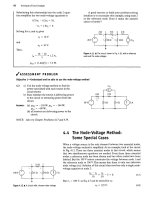
... the independent voltage source is 1.5 A In general, when you use the node-voltage method to solve circuits that have voltage sources connected directly between essential nodes, the number of unknown ... each loop to distinguish it Recall also that the mesh-current method is applicable only to planar circuits The F1gure 4
Ngày tải lên: 06/07/2014, 16:20
Electric Circuits, 9th Edition P14 pps
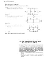
... same for both circuits in the figure for all values of RL If the current through RL is the same in both circuits, then the voltage drop across R{ is the same in both circuits, and the circuits are ... said for the circuits in Fig 4.39(b) Example 4.9 illustrates an application of the equivalent circuits depicted in Fig 4.39 R -wv—»a »« \R, -•b (a) (b) Figure 4.39 • Equivalent circuits containing ... and mesh-current methods are powerful techniques for solving circuits, we are still interested in methods that can be used to simplify circuits Series-parallel reductions and A-to-Y transformations...
Ngày tải lên: 06/07/2014, 16:20

Electric Circuits, 9th Edition P15 docx
... a test voltage source or a test current source to the Thevenin terminals a,b.The Thevenin resistance equals the ratio of the voltage across the test source to the current delivered by the test ... circuit and then excite the circuit from the terminals a,b with either a test voltage source or a test current source If we apply a test voltage source, we will know the voltage of the dependent voltage ... controlling current i Therefore we opt for the test voltage source Figure 4.54 shows the circuit for computing the Thevenin resistance The externally applied test voltage source is denoted vr, and the...
Ngày tải lên: 06/07/2014, 16:20

Electric Circuits, 9th Edition P16 potx
... use the results of sensitivity analysis to determine which component value variation has the greatest impact on the output of the circuit As we can see from the PSpice sensitivity analysis in Table ... were introduced in this chapter: • The node-voltage method works with both planar and nonplanar circuits A reference node is chosen from among the essential nodes Voltage variables are assigned ... is the number of essential nodes (See page 93.) • The mesh-current method works only with planar circuits Mesh currents are assigned to each mesh, and Kirchhoff's voltage law is used to write one...
Ngày tải lên: 06/07/2014, 16:20

Electric Circuits, 9th Edition P20 docx
... concepts underlying these basic elements is in order An inductor is an electrical component that opposes any change in electrical current It is composed of a coil of wire wound around a supporting ... capacitor is an electrical component that consists of two conductors separated by an insulator or dielectric material The capacitor is the only device other than a battery that can store electrical ... capacitors Be assured that the circuit analysis techniques introduced in Chapters and apply to circuits containing inductors and capacitors Therefore, once you understand the terminal behavior...
Ngày tải lên: 06/07/2014, 16:20

Electric Circuits, 9th Edition P21 pdf
... microfarad (/xF) range The graphic symbol for a capacitor is a reminder that capacitance occurs whenever electrical conductors are separated by a dielectric, or insulating, material This condition implies...
Ngày tải lên: 06/07/2014, 16:20

Electric Circuits, 9th Edition P22 potx
... inductance.This notation is needed particularly in circuits containing more than one pair of magnetically coupled coils The easiest way to analyze circuits containing mutual inductance is to use ... inductance is more precisely referred to as self-inductance We now consider the situation in which two circuits are linked by a magnetic field In this case, the voltage induced in the second circuit ... capacitors is left as an exercise (See Problem 6.33.) We say more about series-parallel equivalent circuits of inductors and capacitors in Chapter 7, where we interpret results based on their use...
Ngày tải lên: 06/07/2014, 16:20

Electric Circuits, 9th Edition P23 doc
... forms a voltage divider just as the series resistor circuit did in Chapter In both voltage-divider circuits, the output voltage does not depend on the component values but only on their ratio Here, ... 6.3 for a discussion on how to handle the initial conditions for series and parallel equivalent circuits involving inductors and capacitors (V) Mutual inductance, M, is the circuit parameter relating ... terms of the known behavior of the circuit they purport to describe?" With these thoughts in mind, test the expressions of Example 6.5 by performing the following checks: a) Check the expressions...
Ngày tải lên: 06/07/2014, 16:20
Bạn có muốn tìm thêm với từ khóa: