catia part design sketcher


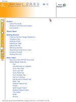
V5R12 part design mechanical design solutions 1 - Thiết kế cơ khí với Catia
Ngày tải lên: 14/03/2014, 18:58
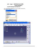
Luận văn tốt nghiệp Part design
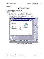
... ta cần phải có một khối Part cho trước và một bề mặt trên khối Part là mặt giới hạn cho khối Part mà ta xây dựng kế tiếp. CATIA cho phép chúng ta xem trước khối part được tạo. Hình 1.21 ... Các Lệnh a. Lệnh PART Tạo một part trong CATIA có nghóa là đùn một biên dạng cho trước theo một hoặc hai hướng. Bài tập này sẽ chỉ cho cho chúng ta cách dựng một khối part cơ bản dựa trên ... trong sketcher hoặc là dựng một Sketch trong môi trường Part bằng cách chọn một trong 3 mặt phẳng mà CATIA cung cấp sẵn ( ngoài trừ những đường thẳng). Hình 1.2 Biên dạng trong Sketcher...
Ngày tải lên: 05/12/2012, 13:56

Tìm hiểu về part design
... trong sketcher hoặc là dựng một Sketch trong môi trường Part bằng cách chọn một trong 3 mặt phẳng mà CATIA cung cấp sẵn ( ngoài trừ những đường thẳng). Hình 1.2 Biên dạng trong Sketcher ... thuộc khối part cho trườc . Bề mặt mà ta lựa chọn sẽ là bề mặt giới hạn cho khối Part mà muốn ta xây dựng. Hình 1.33 Chọn bề mặt giới hạn click Preview để xem trước khối part mà ta vừa ... Part được tạo thành Luận Văn Tốt Nghiệp GVHD: TS. Nguyễn Hoài Sơn SVTH : Phồng cóng Phắn – Nguyễn Cảnh Toàn Trang : 4 III. Hướng Dẫn Chi Tiết Sử Dụng Các Lệnh a. Lệnh PART Tạo một part...
Ngày tải lên: 27/04/2013, 17:46

IELTS Part 2 and Part 3 Topics and Questions -Building Design
... you think they say that? FQ • The Part 2 and all of the Part 3 was copied from Topic 100 with no changes. I am guessing that some changes were made to the Part 3 questions around May 10, 2008 ... this advice? * • Do you yourself ever give people advice? * Part 3 (See also the Part 3 questions for Topic #130 and the Part 3 questions for Topic #59) Note on verbs: You can say: accept, ... ************************************************************ ********** IELTS Part 2 and Part 3 Topics and Questions Page 39 191. A Family Member (Jan. 10, 2009) 192. A Course You Would Like to Study (Jan. 10, 2009) Not Confirmed as a Part 2 Topic 193....
Ngày tải lên: 04/10/2013, 17:20
HVAC Systems Design Handbook part 6
... website. Design Procedures: Part 4 177 Figure 6.21 Tank at pump suction, pumping away from boiler. Figure 6.22 Tank at pump discharge, pumping into boiler. (Not recommended.) Design Procedures: Part ... given at the website. Design Procedures: Part 4 183 Figure 6.30 Vertical in-line pump. (Courtesy of ITT-Bell and Gossett.) Figure 6.31 Pump performance curve. Design Procedures: Part 4 Downloaded ... valves. The reverse-return system (Fig. 6.15) is designed to provide pres- sure differences from supply to return which are similar at all Design Procedures: Part 4 Downloaded from Digital Engineering...
Ngày tải lên: 17/10/2013, 22:15

Catia V5.3 - ASSEMBLY DESIGN mode
... highlighted part. 89 Once on your part, the compass becomes green when active. As you move your cursor over it, different parts will turn orange. The orange part highlighted represents the way the part ... pick the second centerline, Catia will automatically constrain them. If Catia does not immediately line them up, click the UPDATE icon. 92 Once you have moved the parts relative to one another, ... Instantination 84 Assembling your individual parts into one assembly is very simple and user friendly in Catia. The first thing to do is gather up your parts. Here we have a simple plate with a...
Ngày tải lên: 18/10/2013, 12:15
HVAC Systems Design Handbook part 8
... website. 223 Chapter 8 Design Procedures: Part 6 Automatic Controls 8.1 Introduction HVAC systems are sized to satisfy a set of design conditions, which are selected to generate a maximum load. Because these design ... the website. Design Procedures: Part 6 247 Figure 8.30 Flow versus plug lift in a control valve. Figure 8.31 Coil heating capacity versus hot water flow rate. Design Procedures: Part 6 Downloaded ... Use as given at the website. Design Procedures: Part 6 243 Figure 8.25 Wheatstone bridge. Figure 8.26 Bridge circuit with calibration and set point. Design Procedures: Part 6 Downloaded from Digital...
Ngày tải lên: 20/10/2013, 16:15
HVAC Systems Design Handbook part 7
... smaller distribution pipe. Pumping and control may be simplified. System design pressures are similar as for high- Design Procedures: Part 5 Downloaded from Digital Engineering Library @ McGraw-Hill ... periodically slough it off or scrape it off into a tank which is part of the circulated chilled water system. Design Procedures: Part 5 Downloaded from Digital Engineering Library @ McGraw-Hill ... as given at the website. Design Procedures: Part 5 221 ‘‘Steam Systems’’; Chap. 11, ‘‘District Heating and Cooling’’; Chap. 12, ‘‘Hydronic Heating and Cooling System Design ’; and Chap. 14, ‘‘Medium...
Ngày tải lên: 20/10/2013, 16:15
HVAC Systems Design Handbook part 9
... at the website. Equipment: Part 1 309 Figure 9.22 Partial section through a finned coil. Figure 9.23 Heat transfer through a tube wall. that area may look good to the designer, but the system won’t ... detailed and helpful informa- tion to assist designers. However, designers must take care to ensure that they, and not the manufacturer, control the final system design. References 1. F. Beseler, ‘‘Scroll ... density ratio at the design elevation (see Sec. 4.5 and Fig. 4.5). For example, the air density ratio at 5000 ft is 0.826. 2. Select the coil with a face area appropriate to the design (high- altitude)...
Ngày tải lên: 24/10/2013, 15:15

HVAC Systems Design Handbook part 10
... website. 321 Chapter 10 Equipment: Part 2 Heating 10.1 Introduction Heating is the first word in the acronym HVAC. It is the most impor- tant part because without heating mankind would have difficulty in surviving. Proper design ... website. Equipment: Part 2 355 Figure 10.29 Psychrometric chart for Fig. 10.28, without heat recovery. Figure 10.30 Psychrometric chart for Fig. 10.28, with heat recovery. Equipment: Part 2 Downloaded ... package which includes a heating element and a circulating fan. It is designed for installation in or adjacent to Equipment: Part 2 Downloaded from Digital Engineering Library @ McGraw-Hill (www.digitalengineeringlibrary.com) Copyright...
Ngày tải lên: 24/10/2013, 15:15

HVAC Systems Design Handbook part 11
... package equipment. The designer or specifier may re- ject some equipment sources for inadequately handling the design is- sues mentioned. 11.5 Terminal Units A terminal unit is a part of a larger air-handling ... fan-powered mixing box (Fig. 11.17). The fan-powered box is a small fan-and-damper unit designed to circulate Equipment: Part 3 Downloaded from Digital Engineering Library @ McGraw-Hill (www.digitalengineeringlibrary.com) Copyright ... Systems for Air Conveying of Vapors, Gases Mists and Non-Combustible Particulate Solids, NFPA 91-1999. 2. Fundamentals Governing the Design and Operation of Local Exhaust Systems, Amer- ican Industrial...
Ngày tải lên: 28/10/2013, 22:15
HVAC Systems Design Handbook part 12
... The HVAC designer must work closely with the electrical designer to sat- isfy the needs of both disciplines. 12.13 Summary In building construction, HVAC design is interwoven with the electri- cal design, ... mechanical as electrical, perhaps more so. The mechanical HVAC designer needs to understand the unit function to participate effectively in the design. A standby generator, sometimes called an engine-driven ... over into plant design considerations. 12.11 Lighting Systems Lighting design ranges from following a cookbook to a high-level art form. It is not the responsibility of the HVAC designer, but lighting imposes...
Ngày tải lên: 07/11/2013, 19:15
HVAC Systems Design Handbook part 13
... lack of acceptance—of the product, which is the design. Early in the development of computer-aided design (CAD) techniques, it was felt that computer- Design Documentation: Drawings and Specifications Downloaded ... as given at the website. 411 Chapter 13 Design Documentation: Drawings and Specifications 13.1 Introduction Design documents evolve from and include the designer’s calculations, equipment selections, ... but it can and must be mastered by HVAC system designers. The drawings and spec- ifications complement each other, complete the design, and are part of the legally binding commitment of the contractor...
Ngày tải lên: 07/11/2013, 19:15
Bạn có muốn tìm thêm với từ khóa: