1 4 design and compensation of control systems
Design and Optimization of Thermal Systems Episode 1 Part 4 pps
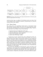
... Simulation of the system Evaluation of different designs Iteration and obtaining an acceptable design Optimization of the system design Automation and control Communicating the final design Figure 2 . 14 ... thermostat control with an on/off mechanism is often used with the designed thermal system to maintain the desired temperature levels 58 Design and Optimization of Thermal Systems 2.2 CONCEPTUAL DESIGN ... the number of design variables Making modifications in existing systems refers to the use of the information available on the design of these systems for developing a conceptual design and not necessarily...
Ngày tải lên: 06/08/2014, 15:20

Design and Optimization of Thermal Systems Episode 1 Part 1 ppsx
... 607 11 .1. 4 Design Methodology 609 11 .1. 5 Application to Thermal Systems 610 11 .2 Additional Constraints 6 21 11. 3 Professional Ethics 623 11 .4 Sources of Information ... Bartz 81 82 83 84 85 86 87 88 89 90 91 92 93 94 95 96 97 98 99 10 0 10 1 10 2 10 3 10 4 10 5 10 6 10 7 10 8 10 9 Mechanism Analysis: Simplified and Graphical Techniques, Second Edition, Revised and Expanded, ... Programming 44 2 7.3 .4 Geometric Programming 44 4 7.3.5 Other Methods 44 4 7 .4 Optimization of Thermal Systems 44 7 7 .4 .1 Important Considerations 44 7 7 .4. 2 Different...
Ngày tải lên: 06/08/2014, 15:20
Design and Optimization of Thermal Systems Episode 1 Part 2 pptx
... components, and subsystems The basic nature of thermal systems will be outlined, and examples of different types of systems will be presented from many diverse and important areas 1. 1 ENGINEERING DESIGN ... Experimental data Analysis and evaluation Acceptable? Yes Acceptable design obtained FIGURE 1. 4 Schematic of a typical design procedure Redesign No Introduction 1. 1.3 SELECTION VERSUS DESIGN We are frequently ... may differ in intensity and sequence 1. 3 THERMAL SYSTEMS Let us now turn our attention to thermal systems and consider the nature of these systems and the various types of systems that are commonly...
Ngày tải lên: 06/08/2014, 15:20
Design and Optimization of Thermal Systems Episode 1 Part 3 pptx
... Stoecker and Jones Introduction FIGURE 1. 19 Photographs of practical heat pumps (From KIST, Korea.) 37 38 Design and Optimization of Thermal Systems (19 82), Cooper (19 87), and Kreider and Rabl (19 94) ... pump (b) FIGURE 1. 11 Power systems based on (a) solar energy and (b) nuclear energy (Adapted from Howell and Buckius, 19 92.) 30 Design and Optimization of Thermal Systems most of which are not ... Ozisik (19 85) and Incropera and Dewitt (20 01) in heat transfer, Fox and McDonald (2003) and Shames (19 92) in fluid mechanics, Howell and Buckius (19 92), Cengel and Boles (2002) and Moran and Shapiro...
Ngày tải lên: 06/08/2014, 15:20
Design and Optimization of Thermal Systems Episode 1 Part 5 ppsx
... A fixed sum of money may also be 94 Design and Optimization of Thermal Systems 74 10 19 47 31 29 44 18 46 49 28 27 17 11 26 48 42 43 32 16 33 41 12 14 13 FIGURE 2.25 The first page of a typical ... D1 and D and the length L, and for different operating conditions, including off -design, given by the flow rates m1 and m2 and the inlet temperatures T1,i and T2,i Basic Considerations in Design ... Figure 2 .19 (a), is to be designed The design variables are the two outer diameters D1 and D2 of the inner and outer tubes, respectively; the two wall thicknesses t1 and t2; and the length L of the...
Ngày tải lên: 06/08/2014, 15:20
Design and Optimization of Thermal Systems Episode 1 Part 6 pdf
... important in the design of FIGURE 2.33 Range of thermal conductivity k for a variety of materials under normal temperature and pressure 11 0 Design and Optimization of Thermal Systems thermal systems ... Incropera, F.P and Dewitt, D.P (20 01) Fundamentals of Heat and Mass Transfer, 5th ed., Wiley, New York Jaluria, Y and Lombardi, D (19 91) Use of expert systems in the design of thermal equipment and processes, ... P2.6(b) 11 8 Design and Optimization of Thermal Systems (c) Extrusion of aluminum from a heated cylindrical block, of diameter 15 cm at a temperature of 600 K, to a rod of diameter cm at the rate of...
Ngày tải lên: 06/08/2014, 15:20

Design and Optimization of Thermal Systems Episode 1 Part 7 pptx
... given profile Such simplifications of the 14 4 Design and Optimization of Thermal Systems boundary conditions not only reduce the complexity of the model, but also make it easier to understand and ... heat 13 4 Design and Optimization of Thermal Systems treatment The flow of hot gases and thermal energy, on the other hand, is studied as a continuum, using a continuous model Both the discrete and ... casing, inner lining, and heating unit of the oven? Briefly justify your answers Modeling of Thermal Systems 3 .1 INTRODUCTION 3 .1. 1 IMPORTANCE OF MODELING IN DESIGN Modeling is one of the most crucial...
Ngày tải lên: 06/08/2014, 15:20
Design and Optimization of Thermal Systems Episode 1 Part 8 doc
... Modeling of Thermal Systems 14 9 T1 T2 T2 Streamlines T2 Isotherms (a) (b) A1 A2 V1 V2 2 ρ1V1A1 = ρ2V2 A2 (c) (d) FIGURE 3 .13 Differential formulations (a) Flow in an enclosed region due to inflow and ... equations 15 6 Design and Optimization of Thermal Systems Wall Insulation (Tw )1 = 500 K (Ti)2 = 300 K x 10 cm 20 cm Temperature (a) 500 K 41 5 .27 K 40 0 K 300 K Distance (b) FIGURE 3 .16 Boundary ... variations of the thermal conductivity k, 15 4 Design and Optimization of Thermal Systems Wall Insulation L D FIGURE 3 .15 The cylindrical furnace, with the wall and insulation, considered in Example 3.4...
Ngày tải lên: 06/08/2014, 15:20

Design and Optimization of Thermal Systems Episode 1 Part 9 pdf
... constants C1, C2, and C3 are obtained as 16 C1 6. 243 C2 0 .11 4C3 9.555 6. 243 C1 8 .17 3C2 0. 044 C3 9 .49 0 0 .11 4C1 0. 044 C2 3 .48 1C3 3.762 These equations are solved to yield the three constants as C1 C2 1. 5039 ... [0.2 0.6 1. 0 1. 8 2.0 3.0 5.0 6.0 8.0]; t0 [ 14 6.0 12 9.5 11 4. 8 90.3 85 .1 63.0 34. 6 25.6 14 .1] ; t log(t0); % Cutve Fit t1 polyfit(tau,t ,1) ; a t1 (1) A exp(t1(2)) Here the input data are entered and the ... 0.9 LR LB 0.6 0.6 0.3 LB BR 0.3 0.0 10 –2 10 1 100 10 1 0.0 10 –2 10 2 10 1 100 Gr/Re2 (a) 10 1 10 2 Gr/Re2 (b) 0.9 LR BR 0.6 0.3 0.0 10 –2 10 1 100 10 1 10 2 Gr/Re (c) FIGURE 3.22 Calculated maximum...
Ngày tải lên: 06/08/2014, 15:20
Design and Optimization of Thermal Systems Episode 1 Part 10 pdf
... 2.0 S 1. 5 10 10 10 3 1. 91 3 .10 4 .11 5.03 3 .48 6.66 7. 51 9 .19 4. 67 7.59 10 .08 12 .33 It is expected from theoretical considerations that Q varies with R and S as ARbSc, where A, b, and c are constants ... 0 .1 0.2 0.3 0 .4 0.5 0.6 0.8 1. 0 1. 2 y: 0.87 1. 82 2.86 4. 0 5.26 6.65 9.88 13 .8 18 .52 3.32 The flow rate F is given at various values of the pressure P as P 0.025 0.05 0 .1 0.2 0.3 0 .4 0.5 F 1. 41 ... transfer, and data analysis, are often governed by linear systems A system of n linear equations may be written in the general form a11x1 a12 x a1n x n b1 a21x1 a22 x a2 n x n b2 an1x1 an x ann...
Ngày tải lên: 06/08/2014, 15:20
Design and Optimization of Thermal Systems Episode 2 Part 1 doc
... 10 1.39 81 97.8263 94. 646 7 91. 843 4 89 .40 22 87. 310 9 85.5588 84 .13 71 83.0388 82.25 81 81. 7 9 14 81. 6360 81. 7 9 14 82.25 81 83.0388 84 .13 71 85.5588 87. 310 9 89 .40 22 91. 843 4 94. 646 7 97.8263 10 1.39 81 105.3803 10 9.7928 ... T (10 ) = T (11 ) = T (12 ) = T (13 ) = T ( 14 ) = T (15 ) = T (16 ) = T (17 ) = T (18 ) = T (19 ) = T(20) = T( 21) = T(22) = T(23) = T( 24) = T(25) = T(26) = T(27) = T(28) = T(29) = 11 4. 6578 10 9.7928 10 5.3803 10 1.39 81 ... 81. 7860 82.2529 83.0337 84 .13 23 85.5 543 87.3067 89.39 84 91. 840 0 94. 643 8 97.8238 10 1.39 61 105.3788 10 9.7 917 11 4. 6573 EPS = 0.000 01 Number of Iterations = 766 T (1) = T(2) = T(3) = T (4) = T(5) = T(6) =...
Ngày tải lên: 06/08/2014, 15:20

Design and Optimization of Thermal Systems Episode 2 Part 4 doc
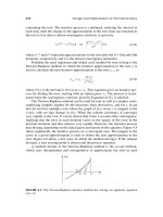
... of the system Evaluation of the design Selection of an acceptable design Optimization of the design follows the determination of a domain of acceptable designs and is not included here Most of ... circuitry 3 04 Design and Optimization of Thermal Systems Library of Previous Designs Any industry involved with the design of systems and equipment would generally develop many successful designs ... volume V gives 10 00 42 00 V (To – 20) 2 .1 105 10 3 Acceptable Design of a Thermal System 317 where the density of water is taken as 10 00 kg/m3 and the specific heat at constant pressure as 42 00 J/(kg...
Ngày tải lên: 06/08/2014, 15:20

Design and Optimization of Thermal Systems Episode 3 Part 1 pot
... equations: U x1 G x1 U x2 0, G x2 0, G x1 0, x1 x U* 36 .49 3, (8 .47 ) 12 (8 .48 ) These equations lead to 4x1 x2 0, Therefore, x* 2 .46 6, x* 4. 866, 2.027 (8 .49 ) It can be shown that if either x1 or x2 is ... Keisler (19 86) and Kaplan (2002), and in books on optimization, such as Fox (19 71) , Beightler et al (19 79), and Chong and Zot (20 01) For the case of two independent variables, x1 and x2, with U(x1, ... following system of equations: U x1 G1 x1 G2 x1 m Gm x1 U x2 G1 x2 G2 x2 m Gm x2 U xn G1 xn G2 xn m Gm xn Lagrange Multipliers 47 7 G1(x1, x2, x3, , xn) G 2(x1, x2, x3, , xn) 0 Gm(x1, x2, x3,...
Ngày tải lên: 06/08/2014, 15:21
Design and Optimization of Thermal Systems Episode 3 Part 4 ppsx
... equations, w1 0. 611 and w2 0.389 Therefore, C* (3.5/0. 611 )0. 611 ( 14 .8/0.389)0.389 11 .965 Then, from Equation (10 .13 ) and Equation (10 . 14 ), 3.5 m1 .4 0. 611 C* which gives m (0. 611 C*/3.5 )1/ 1 .4 1. 692 ... 552 Design and Optimization of Thermal Systems 0 .1 0.05 –0.05 –0 .1 –0 .15 –0.2 –0.25 –0.3 –0.35 –0 .4 –0 .45 10 1 –2 –3 4 –5 –6 –7 –8 –9 10 11 DP 10 –20 10 St –0.5 L2 L1 L2 10 0 0.5 (a) L1 (b) ... treated by geometric programming are U x2 / U U U x1x1/ x1 x1 550 10 5 x1 x1x2 x1 x1 x3.3 (10 .1) (10 .2) 12 0, 000 10 x1 x1 (10 .3) 2 3.7 x2 x3 x2 (10 .4) Similarly, for constrained problems, the following...
Ngày tải lên: 06/08/2014, 15:21

Tài liệu 78 Rapid Design and Prototyping of DSP Systems docx
... forward Int Adds Int Div Comp Int Mult exp Real Add Real Mult — 10 24 66 14 22 16 16 16 16 64 646 20 10 258 15 49 19 3 16 - 10 24 - 12 16 - modeling section, preliminary investigations can be made from ... pp 44 -52, Feb 19 95 [13 ] Gajski, D and Vahid, F., Specification and design of embedded hardware-software systems, IEEE Design & Test of Computers, pp 53-67, Spring 19 95 [ 14 ] DeBardelaben, J and ... Hardware/software codesign for signal processing systems A survey and new results, Proc of the 29th Annual Asilomar Conference on Signals, Systems, and Computers, Nov 19 95 [15 ] IEEE Std 11 64 -19 93...
Ngày tải lên: 25/12/2013, 06:16

design and optimization of thermal systems A Series of Textbooks and Reference Books Founding ppt
... 607 11 .1. 4 Design Methodology 609 11 .1. 5 Application to Thermal Systems 610 11 .2 Additional Constraints 6 21 11. 3 Professional Ethics 623 11 .4 Sources of Information ... Bartz 81 82 83 84 85 86 87 88 89 90 91 92 93 94 95 96 97 98 99 10 0 10 1 10 2 10 3 10 4 10 5 10 6 10 7 10 8 10 9 Mechanism Analysis: Simplified and Graphical Techniques, Second Edition, Revised and Expanded, ... Programming 44 2 7.3 .4 Geometric Programming 44 4 7.3.5 Other Methods 44 4 7 .4 Optimization of Thermal Systems 44 7 7 .4 .1 Important Considerations 44 7 7 .4. 2 Different...
Ngày tải lên: 27/06/2014, 17:20

design and optimization of thermal systems 66 pptx
... 607 11 .1. 4 Design Methodology 609 11 .1. 5 Application to Thermal Systems 610 11 .2 Additional Constraints 6 21 11. 3 Professional Ethics 623 11 .4 Sources of Information ... Bartz 81 82 83 84 85 86 87 88 89 90 91 92 93 94 95 96 97 98 99 10 0 10 1 10 2 10 3 10 4 10 5 10 6 10 7 10 8 10 9 Mechanism Analysis: Simplified and Graphical Techniques, Second Edition, Revised and Expanded, ... Programming 44 2 7.3 .4 Geometric Programming 44 4 7.3.5 Other Methods 44 4 7 .4 Optimization of Thermal Systems 44 7 7 .4 .1 Important Considerations 44 7 7 .4. 2 Different...
Ngày tải lên: 27/06/2014, 17:20

Design and Implementation of VLSI Systems_Lecture 07: Sequential Circuit Sign potx
... Q1 Combinational Logic D2 1 Q2 Combinational Logic D3 L3 2 L2 D1 L1 1 Q3 1 2 Tc D1 t pd t pd t pd Tc tpdq1 2t pdq sequencing overhead Q1 D2 Q2 D3 tpd1 tpdq2 tpd2 26 MAX DELAY: ... sequencing overhead p Q1 D2 Combinational Logic L2 D1 L1 p Q2 Tc D1 (a) tpw > tsetup tpdq Q1 tpd D2 p tpcq Q1 (b) tpw < tsetup D2 Tc tpd tpw tsetup 27 MIN-DELAY: FLIP-FLOPS F1 clk Q1 CL tcd thold ... hold time risk 41 LATCH PLACEMENT & TIME BORROWING 42 LOW-POWER SEQUENTIAL DESIGN 43 TWO-PHASE TIMING TYPES Two phases Three classes: Stable Valid Qualified clock 44 CHARACTERIZING...
Ngày tải lên: 29/07/2014, 16:21
Design and Implementation of VLSI Systems_Lecture 06: Circuit characterization and performance estimation ppt
... 12 .4 ˆ D Nf P 14 11 EXAMPLE Annotate your designs with transistor sizes that achieve this delay 8 8 10 25 25 25 8 Y 25 10 10 10 24 6 12 6 Y 8 16 16 0 * (4/ 3) / 4. 2 = 50 16 16 0 * / 4. 5 ... the two designs H = 16 0 / 16 = 10 B = N = D0 S Y D1 S P 22 G (4 / 3) (4 / 3) 16 / D0 S D1 S Y P 1 F GBH 16 0 / ˆ f N F 4. 2 G (6 / 3) (1) F GBH 20 ˆ f N F 4. 5 ˆ D ... significantly decreases area and power Inverter NAND2 fastest P/N ratio A 1. 41 4 Y gu = 1. 15 gd = 0. 81 gavg = 0.98 NOR2 B Y A B 2 A 2 Y gu = 4/ 3 gd = 4/ 3 gavg = 4/ 3 1 gu = gd = gavg = 3/2 23 OBSERVATIONS...
Ngày tải lên: 29/07/2014, 16:21

Design and Implementation of VLSI Systems_Lecture 05: Circuit Characterzation performace estimation doc
... G )1/ N + P Design NOR4 N G P D 2 34 NAND4-INV 2 29.8 NAND2-NOR2 20/9 30 .1 INV-NAND4-INV NAND4-INV-INV-INV 2 22 .1 21. 1 NAND2-NOR2-INV-INV 20/9 20.5 NAND2-INV-NAND2-INV 16 /9 19 .7 INV-NAND2-INV-NAND2-INV ... 22 .1 Path Delay: Gate sizes: z = 96 *1/ 5.36 = 18 y = 18 *2/5.36 = 6.7 A[3] A[3] 10 10 A[2] A[2] 10 10 A [1] A [1] 10 10 A[0] A[0] 10 10 y z word[0] 96 units of wordline capacitance y z word [15 ] 48 ... 3*5 + = 22 = 4. 4 FO4 40 EXAMPLE: 3-STAGE PATH Work backward for sizes y = 45 * (5/3) / = 15 x = (15 *2) * (5/3) / = 10 x x A P: N: P: x N: y 45 45 P: 12 y N: B B 45 45 41 BEST NUMBER OF STAGES...
Ngày tải lên: 29/07/2014, 16:21