ứng dụng của lò vi sóng
Thiết kế mạch đếm sản phẩm với ứng dụng của họ vi xử lý 8051
... gợi ý của giáo vi n hướng dẫn NGUYỄN MINH QUÂN và qua sự tìm hiểu của các thành vi n trong nhóm,nên chúng em ñã chọn ñề tài nghiên cứu và thiết kế mạch ñếm sản phẩm với ứng dụng của họ vi ñiều ... hội tốt ñể ứng dụng những kiến thức của môn VI XỬ LÝ ñã học vào thực tế. I.2 Mục tiêu của ñề tài Đề tài nhằm mục ñích thiết kế và chế tạo thành công mạch ñếm sản phẩm sử dụng họ vi ñiều khiển ... ứng dụng rất tiện ích sử dụng trong kĩ thuật, trong ñời sống, trong công nghiệp ở các nhà máy và xí nghiệp sản xuất… và cả những tiện nghi trong ngôi nhà của chúng ta. Một trong những ứng dụng...
Ngày tải lên: 25/04/2013, 12:02

Nghiên cứu ứng dụng của bộ vi xử lý trong quản lý thư viện trường tiểu học Kim Đồng
... thanh ghi I/O v thao tỏc ghi li 1 vo bt k c no ó c thit lp ng ngha vi vic xoỏ c ú. Tuy nhiờn, cỏc lnh CBI v SBI ch lm vic vi cỏc thanh ghi cú a ch t $00 n $1F. Chc nng ca mi bit trong cỏc thanh ... mch ni ghộp gia àC vi LCD, keypad, IC LM335 v gia àC vi mỏy tớnh thụng qua cng RS 232. Lp trỡnh phn mm np cho àC thc hin cỏc kt ni trờn. Vit phn mm trờn PC giao tip vi àC qua cng RS 232. ... Vit bỏo cỏo tt nghip. 1.3. Phng hng thc hin. 1.3.1. La chn thit b. a) La chn vi iu khin : Trong thc t cú rt nhiu cỏc h vi x lý khỏc nhau cú th s dng c trong ng dng ny nh h vi...
Ngày tải lên: 27/04/2013, 22:38
Nghiên cứu ứng dụng của bộ vi xử lý trong quản lý thư viện trường tiểu học Kim Đồng
... sinh cỏ cụng vic - Cụng vic: Mt tp hp cỏc x lý cú th thc hin cú chung cỏc s kin khi sinh. - Quy tc ra: L Iu kin th hin cỏc quy tc qun lý, quy nh vic cho ra kt qu cụng vic THệ VIEN ẹIEN Tệ ... hỏi phân tích vi n phải hiểu sâu sắc vấn đề, có năng lực thiết kế nhanh các yếu tố của giải pháp và đánh giá chi phí THÖ VIEÄN ÑIEÄN TÖÛ TRÖÏC TUYEÁN - Kết quả: Sản phẩm của cơng vi c thực hiện ... án của giải pháp Mơ hình logic của hệ thống mới mơ tả cái mà hệ thống mới này sẽ làm. Khi mơ hình này được xác định và chuẩn y bởi người sử dụng, thì phân tích vi n hoặc nhóm phân tích vi n...
Ngày tải lên: 27/04/2013, 22:39

Ứng dụng của máy phát sóng cao tần
... Ứng dụng của máy phát sóng cao tần trong y khoa (Radiofrequence I. Giới thiệu II. Lịch sử phát triển III. Nguyên tắc hoạt động IV. Các bộ phận của máy phát sóng cao tần V. Ảnh hưởng của ... tế bào sẽ vĩnh vi n hư hỏng và bắt đầu hoại tử đông máu , trên 60º C tế bào chết xảy ra gần như lập tức . IV. Các bộ phận của máy II. Lịch sử phát triển : Liệu pháp ứng dụng sóng cao tần trong ... được ứng dụng lần đầu tiên vào khoảng thập niên 90 với vi c điều trị và nghiên cứu trong các vấn đề về thân kinh .Rồi sau đó nó được phát triển lên một bước cao hơn cùng với sự phát triển của...
Ngày tải lên: 29/09/2013, 03:10

Nghiên cứu một số đặc điểm sinh học và khả năng ứng dụng của chủng vi tảo biển dị dưỡng Schizochytrium mangrovei PQ6
Ngày tải lên: 18/04/2014, 17:44
Nghiên cứu công nghệ sản xuất thủy tinh pyrex làm dụng cụ thí nghiệm và dụng cụ lò vi sóng
Ngày tải lên: 20/04/2014, 18:22

Vi sóng (microwave), tính chất, đặc trưng, tổng hợp và ứng dụng các loại vi sóng
Ngày tải lên: 11/06/2014, 23:49


Những ứng dụng của đồng vị phóng xạ và công nghệ bức xạ docx
Ngày tải lên: 22/07/2014, 07:21

CẤU TẠO, NGUYÊN TẮC HOẠT ĐỘNG, GIẢI THÍCH HIỆN TƯỢNG CỦA LÒ VI SÓNG VÀ BẾP ĐIỆN TỪ,VẬT LIỆU SIÊU DẪN, CÁC ĐẶC TÍNH CỦA VẬT LIỆU SIÊU DẪN pot
Ngày tải lên: 24/07/2014, 23:20


Microstrip bộ lọc cho các ứng dụng lò vi sóng RF (P1)
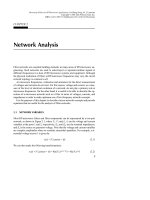
... wavelengths between 1 m (10 –6 m) and 1 mm. Beyond the infrared spectrum is the visible optical spectrum, the ultraviolet spectrum, and x-rays. Below the microwave frequency spectrum is the radio ... tuning. Here the costs for the design and tuning can be reduced greatly by using CAD, which can provide more accurate design with less design iterations, leading to first-pass or tuneless filters. ... developments in this area are cer- tainly being stimulated by increasing computer power. Another driving force for the developments is the requirement of CAD for low-cost and high-volume production. In...
Ngày tải lên: 24/10/2013, 16:15
Microstrip bộ lọc cho các ứng dụng lò vi sóng RF (P2)
... ports of the network NЈЈ ; and all the S submatrices con- tain the corresponding S parameters. Obviously, p + c = M 1 and q + c = M 2 . It is [aЉ] q [aЉ] c [SЉ] qc [SЉ] cc [SЉ] qq [SЉ] cq [bЉ] q [bЉ] c [aЈ] p [aЈ] c [SЈ] pc [SЈ] cc [SЈ] pp [SЈ] cp [bЈ] p [bЈ] c b i ᎏ a j a 1 a 2 Ӈ a M S 1M S 2M Ӈ S MM ... at port 2 of the network NЈ and port 1 of the network N Љ when SЈ mn and SЉ mn are evaluated individually. 2.8 NETWORK PARAMETER CONVERSIONS From the above discussions it can be seen that for ... composite network is given simply by the sum of the short-circuit admittance matrices of the individual networks. Analogously, the networks of Figure 2.3(b) are connected in series at both their input...
Ngày tải lên: 24/10/2013, 16:15
Microstrip bộ lọc cho các ứng dụng lò vi sóng RF (P3)
... the same 3 pole Butterworth lowpass prototype as that used previously in Section 3.3.1, Figure 3.15(b) illustrates a bandpass having a passband from 1 to 2 GHz obtained using the element transformation. 3.3.4 ... = 1 to n (3.24) g n+1 = 1.0 For convenience, Table 3.1 gives element values for such filters having n = 1 to 9. As can be seen, the two-port Butterworth filters considered here are always sym- metrical ... be chosen. 3.2.2 Chebyshev Lowpass Prototype Filters For Chebyshev lowpass prototype filters having a transfer function given in (3.9) with a passband ripple L Ar dB and the cutoff frequency...
Ngày tải lên: 28/10/2013, 23:15
Microstrip bộ lọc cho các ứng dụng lò vi sóng RF (P4)
... previous expressions for re are obtained based on the quasi-TEM or quasistatic approximation, and therefore are rigorous only with DC. At low microwave frequencies, these expressions provide ... expressions also provide accuracy better than one percent. If more accurate values are needed, an iterative or optimization process based on the more accurate analysis models described previously can ... 4.10(h). These microstrip patch resonators can be analyzed as waveguide cavities with mag- netic walls on the sides. The fields within the cavities can be expanded by the TM Z nm0 modes, where z is perpendicular...
Ngày tải lên: 28/10/2013, 23:15

Microstrip bộ lọc cho các ứng dụng lò vi sóng RF (P5)
... Semilumped Lowpass Filters Having Finite-Frequency Attenuation Poles The previous two types of microstrip lowpass filter realize the lowpass prototype filters having their frequencies of infinite ... (b) can only be electrically equivalent to the combline filter in the vicinity of the mid- band frequency, and its stopband behavior is different from that of the combline fil- ter. Similar to the ... inductances L 1 , L 3 , and L 5 block transmission by having infinite series reactance, whereas the capacitance C 6 shorts out transmission by having infinite shunt susceptance. A microstrip filter...
Ngày tải lên: 07/11/2013, 21:15

Microstrip bộ lọc cho các ứng dụng lò vi sóng RF (P6)
... design this type of filter, let us consider the design of an op- timum distributed highpass filter having a cutoff frequency f c = 1.5 GHz and a 0.1 dB ripple passband up to 6.5 GHz. Referring to Figure ... = 1 to n where b i are the susceptance slope parameters of series parallel resonators. It is obvious that for a chosen lowpass prototype, with known element values, the desired reactance/susceptance ... relative dielectric constant of 10.8 and a thickness of 1.27 mm. The bandstop filter is designed to provide an RF rejection better than 40 dB over an operating frequency band from 3.5 GHz to 5.5 GHz....
Ngày tải lên: 07/11/2013, 21:15

Microstrip bộ lọc cho các ứng dụng lò vi sóng RF (P7)
... (MEMS) provide a class of new devices and com- ponents which display superior high-frequency performance and enable new system capabilities. For a general definition, a MEMS is a miniature device ... ability to effectively improve filter selectivity. Therefore, it does not constitute a particularly attractive choice for achieving frequency selectivity. Never- theless, it may be of interest ... production. The change in permittivity as a func- tion of electric field is the key to a wide range of applications. Frequency-agile filters are among many other device applications of ferro- electrics....
Ngày tải lên: 07/11/2013, 21:15