Mechanical Science HandbooksMechanical Science Handbooks 10000 Part 5 pps
Mechanical Science HandbooksMechanical Science Handbooks 10000 Part 5 pps
... is ~ 85 psia. When the piston has traveled to 3 .53 0 inches of its stroke the volume is again halved and temperature reaches ~640°F and pressure 277 psia. When the piston has traveled to 3. 757 inches ... Compression Figure 24 2-Stroke Fuel Injection Power Figure 25 2-Stroke Power The power stroke starts after the piston passes TDC. Figure 25 illustrates the power stroke which continues u...
Ngày tải lên: 21/07/2014, 17:20
Mechanical Science HandbooksMechanical Science Handbooks 10000 Part 13 pps
Ngày tải lên: 21/07/2014, 17:20
Mechanical Science HandbooksMechanical Science Handbooks 10000 Part 6 pps
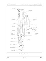
... hydraulic piston and a set of mechanical flyweights, which are driven by the engine blower shaft. Figure 28 provides an illustration of a functional diagram of a mechanical- hydraulic governor. ... resets the fuel rack for increased/decreased fuel. Figure 28 Simplified Mechanical- Hydraulic Governor Rev. 0 ME-01 Page 35 Diesel Engine Fundamentals DOE-HDBK-1018/1-93 DIESEL ENGINE SPEED, F...
Ngày tải lên: 21/07/2014, 17:20

Mechanical Science HandbooksMechanical Science Handbooks 10000 Part 1 ppsx
... DOE-HDBK-1018/1-93 JANUARY 1993 DOE FUNDAMENTALS HANDBOOK MECHANICAL SCIENCE Volume 1 of 2 U.S. Department of Energy FSC-6910 Washington, D.C. 2 058 5 Distribution Statement A. Approved for public release; ... Technical Information Services, U.S. Department of Commerce, 52 85 Port Royal., Springfield, VA 22161. Order No. DE93012178 DOE-HDBK-1018/1-93 MECHANICAL SCIENCE Rev. 0 ME OVE...
Ngày tải lên: 21/07/2014, 17:20
Mechanical Science HandbooksMechanical Science Handbooks 20000 Part 5 doc
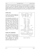
... for services where dirt or other particles may be present in the fluid, where noise is objectionable, or where positive shutoff is required. Rev. 0 ME-04 Page 35 Valves DOE-HDBK-1018/2-93 VALVE ... same techniques as is used for globe valves. Piston Check Valves Figure 25 Piston Check Valve A piston check valve, illustrated in Figure 25, is essentially a lift check valve. It has a dashpot...
Ngày tải lên: 21/07/2014, 17:20
Mechanical Science HandbooksMechanical Science Handbooks 10000 Part 12 pot
... self- priming features, it is essential that all clearances between rotating parts, and between rotating and stationary parts, be kept to a minimum in order to reduce slippage. Slippage is leakage ... displacement piston. The pump will function when a diaphragm is forced into reciprocating motion by mechanical linkage, compressed air, or fluid from a pulsating, external source. The pump con...
Ngày tải lên: 21/07/2014, 17:20
Mechanical Science HandbooksMechanical Science Handbooks 10000 Part 11 doc
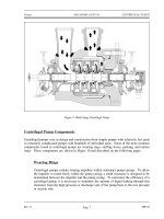
... DOE-HDBK-1018/1-93 Pumps Mechanical Seals In some situations, packing material is not adequate for sealing the shaft. One common alternative method for sealing the shaft is with mechanical seals. Mechanical ... in design and construction from simple pumps with relatively few parts to extremely complicated pumps with hundreds of individual parts. Some of the most common components found...
Ngày tải lên: 21/07/2014, 17:20

Mechanical Science HandbooksMechanical Science Handbooks 10000 Part 10 docx
... impellers are also referred to as shrouded impellers. Figure 5 illustrates examples of open, semi-open, and enclosed impellers. Figure 5 Open, Semi-Open, and Enclosed Impellers The impeller sometimes ... vanes of the rotating impeller impart a radial and rotary motion to the liquid, forcing it to the outer periphery of the pump casing where it is collected in the outer part of the pump...
Ngày tải lên: 21/07/2014, 17:20

Mechanical Science HandbooksMechanical Science Handbooks 10000 Part 9 pptx
... 13 Centrifugal Pump Characteristic Curves 14 Centrifugal Pump Protection 15 Gas Binding 15 Priming Centrifugal Pumps 15 Summary 16 POSITIVE DISPLACEMENT PUMPS 18 Introduction 18 Principle of Operation ... 27 Positive Displacement Pump Protection 28 Summary 28 Rev. 0 ME-03 Page i Department of Energy Fundamentals Handbook MECHANICAL SCIENCE Module 3 Pumps Heat Exchangers DOE-HDBK-1018/...
Ngày tải lên: 21/07/2014, 17:20
Mechanical Science HandbooksMechanical Science Handbooks 10000 Part 8 doc
... 200°F T 1out = 1 45 F U o = 70 BTU/hr-ft 2 -°F A o = 75ft 2 T 2 = represents the cold fluid temperature T 2in =80°F T 2out = 120°F Counter flow ∆T lm = (200 120 o F) (1 45 80 o F) ln (200 120 o F) (1 45 80 o F) ... EXCHANGERS DOE-HDBK-1018/1-93 Heat Exchangers Parallel flow ∆T lm = (200 80 o F) (1 45 120 o F) ln (200 80 o F) (1 45 120 o F) 61 o F Inserting the above values into...
Ngày tải lên: 21/07/2014, 17:20