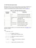
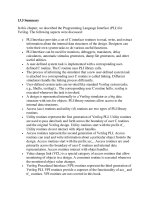
Sequential Verulog Topics part 4 doc

Sequential Verulog Topics part 4 doc
... switches. The gate and the switch-level circuit diagram for the nor gate are shown in Figure 11 -4 . Figure 11 -4. Gate and Switch Diagram for Nor Gate Using the switch primitives discussed in Section ... Switch-Modeling Elements, the Verilog description of the circuit is shown in Example 11 -4 below. Example 11 -4 Switch-Level Verilog for Nor Gate //Define our own nor gate, my_nor...
Ngày tải lên: 01/07/2014, 21:20

Sequential Verulog Topics part 13 docx
... get newspaper #80 coin = 1; #40 coin = 0; #80 coin = 1; #40 coin = 0; #80 coin = 1; #40 coin = 0; 14. 7 Example of Sequential Circuit Synthesis In Section 14. 4.2 , An Example of RTL-to-Gates, ... Figure 14- 10. Finite State Machine for Newspaper Vending Machine 14. 7 .4 Verilog Description The Verilog RTL description for the finite state machine is shown in Example 14- 6....
Ngày tải lên: 01/07/2014, 21:20

Sequential Verulog Topics part 14 doc
... acceleration [2] can often accelerate simulations by two to three orders of magnitude. 14. 9 Exercises 1: A 4- bit full adder with carry lookahead was defined in Example 6-5 on p age 109, using ... stimulus to the RTL and the gate-level netlist and compare the outputs. 4: Write the Verilog RTL description for a 4- bit binary counter with synchronous reset that is active high. (...
Ngày tải lên: 01/07/2014, 21:20

Sequential Verulog Topics part 7 ppt
... combination of the inputs. • Sequential UDPs are used to define blocks with timing controls. Blocks such as latches or flipflops can be described with sequential UDPs. Sequential UDPs are modeled ... table is the most important component of UDP specification. • UDPs can be combinational or sequential. Sequential UDPs can be edge- or level-sensitive. • Combinational UDPs are us...
Ngày tải lên: 01/07/2014, 21:20

Sequential Verulog Topics part 8 ppsx
... are also specified. 13 .4. 1 Access Routines Access routines are also popularly called acc routines. Access routines can do the following: • Read information about a particular object from the ... the example of a simple 2-to- 1 multiplexer whose gate level circuit is shown in Figure 13 -4 . Figure 13 -4. 2-to-1 Multiplexer The Verilog description of the circuit is shown in Example 1...
Ngày tải lên: 01/07/2014, 21:20

Sequential Verulog Topics part 9 ppsx
... the designer's mind was used as the logic synthesis tool, as illustrated in Figure 14- 1 . Figure 14- 1. Designer's Mind as the Logic Synthesis Tool The advent of computer-aided logic ... one of the popular HDLs for the writing of high-level descriptions. Figure 14- 2 illustrates the process. Figure 14- 2. Basic Computer-Aided Logic Synthesis Process Automated logic synth...
Ngày tải lên: 01/07/2014, 21:20

Sequential Verulog Topics part 10 pps
... c_out = c; The always statement The always statement can be used to infer sequential and combinational logic. For sequential logic, the always statement must be controlled by the change in ... (s) ? i1 : i0; It frequently translates to the gate-level representation shown in Figure 14- 3 . Figure 14- 3. Multiplexer Description The if-else statement Single if-else statements transl...
Ngày tải lên: 01/07/2014, 21:20

Sequential Verulog Topics part 1 ppt
... specparam t_01 = 9, t_10 = 13, t_0z = 11; specparam t_z1 = 9, t_1z = 11, t_z0 = 13; specparam t_0x = 4, t_x1 = 13, t_1x = 5; specparam t_x0 = 9, t_xz = 11, t_zx = 7; (clk => q) = (t_01, t_10, ... wire e, f; //Delay is distributed to each gate. and #5 a1(e, a, b); and #7 a2(f, c, d); and #4 a3(out, e, f); endmodule //Distributed delays in data flow definition of a module...
Ngày tải lên: 01/07/2014, 21:20

Sequential Verulog Topics part 3 ppt
... Zero, one, or two delays can be specified for bidirectional switches, as shown in Table 11 -4 . Table 11 -4. Delay Specification for Bidirectional Switches Switch Element Delay Specification Examples ... Bidirectional switches are typically used to provide isolation between buses or signals. 11.1 .4 Power and Ground The power (Vdd, logic 1) and Ground (Vss, logic 0) sources are neede...
Ngày tải lên: 01/07/2014, 21:20

Sequential Verulog Topics part 5 ppt
... and udp_or. Let us design a bigger combinational UDP, a 4- to-1 multiplexer. A 4- to-1 multiplexer was designed with gates in Section 5.1 .4 , Examples. In this section, we describe the multiplexer ... Example 12-5 . Example 12-5 Verilog Description of 4- to-1 Multiplexer with UDP // 4- to-1 multiplexer. Define it as a primitive p rimitive mux4_to_1 ( output out, input i0, i1, i2...
Ngày tải lên: 01/07/2014, 21:20