Sequential Verulog Topics part 3 ppt

Sequential Verulog Topics part 3 ppt
... and tranif1. tran tranif0 tranif1 Symbols for these switches are shown in Figure 11 -3 below. Figure 11 -3. Bidirectional Switches The tran switch acts as a buffer between the two signals ... control signal is a logical 1. These switches are instantiated as shown in Example 11 -3 . Example 11 -3 Instantiation of Bidirectional Switches tran t1(inout1, inout2); //instance name t1...
Ngày tải lên: 01/07/2014, 21:20
Sequential Verulog Topics part 7 ppt
... combination of the inputs. • Sequential UDPs are used to define blocks with timing controls. Blocks such as latches or flipflops can be described with sequential UDPs. Sequential UDPs are modeled ... sections will follow the same process. Figure 13- 2 summarizes the general process of adding and invoking a user-defined system task. Figure 13- 2. General Flow of PLI Task Addition a...
Ngày tải lên: 01/07/2014, 21:20

Sequential Verulog Topics part 1 ppt
... concisely. //a [31 :0] is a 32 -bit vector and out[15:0] is a 16-bit vector //Delay of 9 between each bit of a and every bit of out specify ( a *> out) = 9; // you would need 32 X 16 = 35 2 parallel ... Figure 10 -3 , we take the example in Figure 10-1 and compute the pin-to-pin delays for each input/output p ath. Figure 10 -3. Pin-to-Pin Delay Pin-to-pin delays for standa...
Ngày tải lên: 01/07/2014, 21:20

Sequential Verulog Topics part 5 ppt
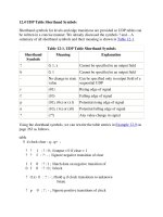
... mux4_to_1 ( output out, input i0, i1, i2, i3, s1, s0); table // i0 i1 i2 i3, s1 s0 : out 1 ? ? ? 0 0 : 1 ; 0 ? ? ? 0 0 : 0 ; treated as x values. 12.2 .3 Shorthand Notation for Don't Cares ... UDP basics In this section, we describe parts of a UDP definition and rules for UDPs. 12.1.1 Parts of UDP Definition Figure 12-1 shows the distinct parts of a basic UDP definition i...
Ngày tải lên: 01/07/2014, 21:20

Sequential Verulog Topics part 8 ppsx
... are interconnected. A conceptual internal representation of a module is shown in Figure 13- 3 . Figure 13- 3. Conceptual Internal Representation a Module Each set contains all elements of that ... routine my_monitor, which implements the user-defined system task, is shown in Example 13- 3 . Example 13- 3 PLI Routine to Monitor Nets for Value Changes #include "acc_user.h" to...
Ngày tải lên: 01/07/2014, 21:20
Sequential Verulog Topics part 9 ppsx
... would consider design constraints such as timing, area, testability, and power. The designer would partition the design into high-level blocks, draw them on a piece of paper or a computer terminal, ... spend more time on designing at a higher level of representation, because less time is required 13. 5 Summary In this chapter, we described the Programming Language Interface (PLI) for V...
Ngày tải lên: 01/07/2014, 21:20

Sequential Verulog Topics part 10 pps
... c_out = c; The always statement The always statement can be used to infer sequential and combinational logic. For sequential logic, the always statement must be controlled by the change in ... ? i1 : i0; It frequently translates to the gate-level representation shown in Figure 14 -3 . Figure 14 -3. Multiplexer Description The if-else statement Single if-else statements translate...
Ngày tải lên: 01/07/2014, 21:20


Sequential Verulog Topics part 13 docx
... \PRES_STATE[1] , n289, n300, n301, n302, \PRES_STATE2 43[ 1] , n3 03, n304, \PRES_STATE[0] , n290, n291, n292, n2 93, n294, n295, n296, n297, n298, n299, \PRES_STATE2 43[ 0] ; PDFF \PRES_STATE_reg[1] ... U1 13 ( .in0(n295), .in1(n292), .out(n294) ); VNOT U126 ( .in(coin[1]), .out(n2 93) ); VNAND U112 ( .in0(coin[0]), .in1(n2 93) , .out(n292) ); VNAND U125 ( .in0(n294), .in1(n3 03...
Ngày tải lên: 01/07/2014, 21:20

Sequential Verulog Topics part 14 doc
... to the RTL and the gate-level netlist and compare the output. 3: Design a 3- to-8 decoder, using a Verilog RTL description. A 3- bit input a[2:0] is provided to the decoder. The output of the ... similar to those used for Verilog HDL simulators and are discussed in Section 15.1 .3 , Simulation. 15.1 .3 Simulation There are three ways to simulate a design: software simulation, hardw...
Ngày tải lên: 01/07/2014, 21:20