Sequential Verulog Topics part 1 ppt

Sequential Verulog Topics part 1 ppt
... specparam t_ 01 = 9, t _10 = 13 , t_0z = 11 ; specparam t_z1 = 9, t_1z = 11 , t_z0 = 13 ; specparam t_0x = 4, t_x1 = 13 , t_1x = 5; specparam t_x0 = 9, t_xz = 11 , t_zx = 7; (clk => q) = (t_ 01, t _10 , t_0z, ... 0-> ;1, 1- >0, 0->z, z-> ;1, 1- >z, z->0. Order //must be followed strictly. specparam t_ 01 = 9, t _10 = 13 , t_0z = 11 ; specparam t_z1 = 9,...
Ngày tải lên: 01/07/2014, 21:20

Sequential Verulog Topics part 7 ppt
... considered. [ Team LiB ] [ Team LiB ] 12 .7 Exercises 1: Design a 2-to -1 multiplexer by using UDP. The select signal is s, inputs are i0, i1, and the output is out. If the select signal ... clock, and p reset. Output is q. If clock = 0, then q = d. If clock = 1 or x, then q is unchanged. If preset = 1, then q = 1. If preset = 0, then q is decided by clock and d signals. If p...
Ngày tải lên: 01/07/2014, 21:20

Sequential Verulog Topics part 3 ppt
... Figure 11 -1 . Figure 11 -1. NMOS and PMOS Switches In Verilog, nmos and pmos switches are instantiated as shown in Example 11 -1 . Example 11 -1 Instantiation of NMOS and PMOS Switches nmos n1(out, ... tranif1 switch conducts if the control signal is a logical 1. These switches are instantiated as shown in Example 11 -3 . Example 11 -3 Instantiation of Bidirectional Switc...
Ngày tải lên: 01/07/2014, 21:20

Sequential Verulog Topics part 5 ppt
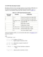
... entry must appear in the same order as ? 1 ? ? 0 1 : 1 ; ? 0 ? ? 0 1 : 0 ; ? ? 1 ? 1 0 : 1 ; ? ? 0 ? 1 0 : 0 ; ? ? ? 1 1 1 : 1 ; ? ? ? 0 1 1 : 0 ; ? ? ? ? x ? : x ; ? ? ? ? ? x ... Example 12 -3 . Example 12 -3 Primitive udp_or p rimitive udp_or(out, a, b); output out; input a, b; table // a b : out; 0 0 : 0; 0 1 : 1; 1 0 : 1;...
Ngày tải lên: 01/07/2014, 21:20

Sequential Verulog Topics part 8 ppsx
... I0 =1& apos;b0; I1 =1& apos;b1; S = 1& apos;b0; #5 I0 =1& apos;b1; I1 =1& apos;b1; S = 1& apos;b1; #5 I0 =1& apos;b0; I1 =1& apos;b1; S = 1& apos;bx; #5 I0 =1& apos;b1; I1 =1& apos;b1; S = 1& apos;b1; end endmodule ... #5 I0 =1& apos;b1; I1 =1& apos;b1; S = 1& apos;b1; $my_stop_finish(0 ,1) ; //Stop simulation. Print module instance name #5 I0 =1& apos;b0; I1 =1& apos;b1; S...
Ngày tải lên: 01/07/2014, 21:20

Sequential Verulog Topics part 9 ppsx
... the designer's mind was used as the logic synthesis tool, as illustrated in Figure 14 -1 . Figure 14 -1. Designer's Mind as the Logic Synthesis Tool The advent of computer-aided logic ... change the timing constraint from 20 ns to 15 ns and resynthesize the design to get the new gate-level netlist that is optimized to achieve a cycle time of 15 ns. • Logic synthesis too...
Ngày tải lên: 01/07/2014, 21:20

Sequential Verulog Topics part 10 pps
... Reduction & ~& | reduction and reduction nand reduction or 1& apos;b0 : out = i0; 1& apos;b1 : out = i1; endcase Large case statements may be used to infer large multiplexers. ... given in Table 14 -1 . The capabilities of individual logic synthesis tools may vary. The constructs that are typically acceptable to logic synthesis tools are also shown. Table 14 -1. Ve...
Ngày tải lên: 01/07/2014, 21:20

Sequential Verulog Topics part 4 doc
... modeling. 11 .2.2 2-to -1 Multiplexer Figure 11 -6. CMOS flipflop The switches C1 and C2 are CMOS switches, discussed in Section 11 .1. 2 , CMOS Switches. Switch C1 is closed if clk = 1, and switch ... my_nor n1(OUT, A, B); //Apply stimulus initial begin //test all possible combinations A = 1& apos;b0; B = 1& apos;b0; #5 A = 1& apos;b0; B = 1& apos;b1; #5 A = 1& a...
Ngày tải lên: 01/07/2014, 21:20

Sequential Verulog Topics part 13 docx
... VOR U 119 ( .in0(n292), .in1(n295), .out(n302) ); VAND U 118 ( .in0(\PRES_STATE[0] ), .in1(\PRES_STATE [1] ), .out(newspaper)); VNAND U 117 ( .in0(n300), .in1(n3 01) , .out(n2 91) ); VNOR U 116 ... VNAND U125 ( .in0(n294), .in1(n303), .out(n300) ); VNOR U 111 ( .in0(n2 91) , .in1(reset), .out(\PRES_STATE243[0] ) ); VNAND U124 ( .in0(\PRES_STATE[0] ), .in1(n304), .out(n3 01) ); V...
Ngày tải lên: 01/07/2014, 21:20

Sequential Verulog Topics part 14 doc
... is done separately. Figure 15 -1. Traditional Verification Flow As shown in Figure 15 -1 , the traditional verification flow consists of the following steps: 1. The chip architect first needs ... Team LiB ] [ Team LiB ] 15 .1 Traditional Verification Flow A traditional verification flow consisting of certain standard components is illustrated in Figure 15 -1 . This flow add...
Ngày tải lên: 01/07/2014, 21:20