programmable logic controllers textbook w plc simulation software

Tài liệu PLC MELSEC System Q Programmable Logic Controllers
... follow-up function. The processing, which will be performed when another transition condition is satisfied with the step immediately after coupling being active, can be selected between STOP, WAIT ... the next step, the coil will be switched OFF at any of the following times: (a) When the end step of the corresponding block is executed. (Except when SM327 is ON) (b) When an SFC control instruction ... QCPU High Performance model QCPU Process CPU SW4D5C-GPPW or later GX Developer Version 7.10L (SW7D5C-GPPW) or later GX Developer Version 8 (SW8D5C-GPPW) or later : Usable, : Unusable 2 4 - 1 4...
Ngày tải lên: 15/10/2013, 16:28

Tài liệu Programmable logic controllers Basic level TP301 – Textbook ppt
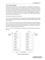
... elimination. This textbook explains the design of a programmable logic controller and its interaction with peripherals. One of the main focal points of the textbook deals with the new interna- tional ... 1 The PLC in automation technology 1.1 Introduction The first Programmable Logic Controller (PLC) was developed by a group of engineers at General Motors in 1968, when the company were looking ... to a logic 0-signal. When working with contactless components, this can give rise to certain tolerance bands. For this reason, certain voltage ranges have been defined as logic 0 or logic...
Ngày tải lên: 22/12/2013, 18:16


Programmable logic controllers 5ed P1
... outputs already inside the controller Program PLC Inputs Outputs Figure 1.3: A programmable logic controller. www.newnespress.com Programmable Logic Controllers 3 Pipe connections, that is, the ... a switch to determine Motor Relay to switch on large current to motor Low voltage Switch Figure 1.2: A control circuit. Drill Workpiece Switch contacts close when workpiece in position Switch ... pole/double throw (SPDT) switch is to use two NAND logic gates (see Chapters 3 and 5), as illustrated in Figure 2.4a. When the switch is in position A, the output is a logic 1. When the switch moves...
Ngày tải lên: 10/04/2014, 14:10

Programmable logic controllers 5ed P2
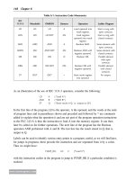
... D-type connector. www.newnespress.com 88 Chapter 4 When we have a positive number, we sign the normal binary number with a 0, that is, we write only negative numbers in the two’s complement form. ... 2 Up/down arm Valve 3 Clockwise/anticlockwise base rotation Valve 4 Extend/retract Open/close Up/down Rotate clockwise/anticlockwise A A A A B B B B Figure 2.41: Robot controls. www.newnespress.com Input/Output ... 8-bit signed two’s complement for À2. If we wanted to add two negative numbers, we would obtain the signed two’s complement for each number and then add them. Whenever a number is negative, we use the...
Ngày tải lên: 10/04/2014, 14:12
Programmable logic controllers 5ed P3
... input Switch Motor (a) L1 L2 Power rails L1 L2 Switch Motor M (b) Figure 5.1: Ways of drawing the same electrical circuit. L1 L2 M 1 2 Holdin g switch Figure 5.2: Stop/start switch. www.newnespress.com 112 ... Gate Output A B Inputs Output =1 A B Inputs >1 Figure 5.26: Logic gate symbols. www.newnespress.com 128 Chapter 5 23. Figure 5.56 shows a ladder diagram. Which of the diagrams showing inputs and output signals would occur with that ladder ... Allen-Bradley PLCs, MELSOFTÀGX Developer for Mitsubishi PLCs, and STEP 7ÀMicro/WIN V4 for Siemens PLCs. The software operates on the Windows operating system and involves selecting items, in the usual Windows...
Ngày tải lên: 10/04/2014, 14:14
Programmable logic controllers 5ed P4
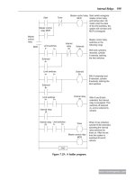
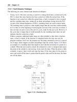
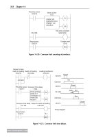
... 7.27: A valve system. www.newnespress.com Internal Relays 197 Figures 7.9b and 7.9c show the built-in facilities with Allen-Bradley and Mitsubishi PLCs. With the Mitsubishi PLC (Figure 7.9c), the ... First, however, we show how latching might be used with such systems to maintain actions. Consider a pneumatic system with single-solenoid controlled valves and involving two cylinders A and B with ... the situation with, say, part of the washing cycle of a domestic washing machine where the drum is to be filled with water, and then when the drum is full, a heater has to be switched on and...
Ngày tải lên: 10/04/2014, 14:16
Programmable logic controllers 5ed P5
... sequencer. www.newnespress.com 248 Chapter 10 Problems 4 through 6 refer to Figure 9.21, which shows two alternative versions of a ladder diagram with two inputs (In 1 and In 2), two outputs ... timers. www.newnespress.com Timers 223 • The count-up overflow (OV) bit is 1 when the up-counter increments above the maximum positive value. ã The count-down underflow (UN) bit is 1 when the ... the task. www.newnespress.com 244 Chapter 10 (ii) Because the internal relay IR 1 is battery-backed, once there is an output from Output 1, it will continue, even when the power is switched off,...
Ngày tải lên: 10/04/2014, 14:18
Programmable logic controllers 5ed P6
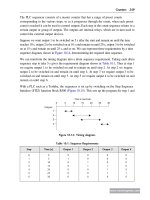
... testing the software. www.newnespress.com 298 Chapter 13 outputs Out 1, followed by Out 2, followed by Out 3, followed by Out 4. Figure 11.1b shows the sequence of signals. Figure 11.2 shows the ... switch open 1 = switch closed Figure 12.1: Thumbwheel switch. www.newnespress.com 274 Chapter 12 • Integral mode, in which the controller output is proportional to the integral of the error with ... for systems that will carry out the following tasks: (a) Switch on a pump when the water level in a tank rises to above 1.2 m and switch it off when it falls below 1.0 m. (b) Switch on a pump;...
Ngày tải lên: 10/04/2014, 14:20
Programmable logic controllers 5ed P7
... B3 + 22 23 24 25 14 498 [26] ]/[+ Saw_Lower Slow_SOV O:033 Saw_Lower Fast_SOV O:033 ]/[ 11 [22] > 499 10 11 ( ) ( ) ( ) Saw_Hyd_Pump Healthy B3 Saw_Lower Healthy O:033 Saw_Lower Fast_SOV O:033 > > 10 [23] www.newnespress.com Designing ... ) Saw_Tension Decrease_PB I:030 +32 05 13 [32] Saw_Tension Decrease_SOV O:033 +31 www.newnespress.com 320 Chapter 13 Bundle Cutting Saw Saw Desk Lamps Stacking Machine Page:00016File #14 Saw ... output will also not www.newnespress.com 344 Chapter 14 Bundle Cutting Saw Saw Cutting Length Lamps (from PECs) Stacking Machine Page:00020File #14 Saw Proj: FLATS3 21:08 12/05/02 58 57 56 55 West_Saw_Cut Photocell ...
Ngày tải lên: 10/04/2014, 14:22


PLC (Programmable Logic Controller) , điều khiển Logic Lập trình được pptx
Ngày tải lên: 02/07/2014, 09:20

BÀI BÁO CÁO THỰC TẬP-THIẾT BỊ ĐIỀU KHIỂN LOGIC KHẢ TRÌNH PLC-Programmable Logic Control
Ngày tải lên: 02/06/2015, 17:34


Tài liệu Thiết kế hệ PLC Phần I: giới thiệu chung về điều khiển LOGIC và thiết bị PLC doc
... logic để thi hành kết thúc điều khiển hệ thống. http://www.ebook.edu.vn Đại Học S Phạm Kỹ Thuật Hng yên Thiết kế hệ PLC Lê Thnh Sơn \ 27 [ 6 External Memory Write ... SCON 00h 22 Power Control PCON 0xx0 0000b http://www.ebook.edu.vn Đại Học S Phạm Kỹ Thuật Hng yên Thiết kế hệ PLC Lê Thnh Sơn \ 3 [ 1. 2 . Khái niệm chung - ứng dụng của PLC. 1.2. 1 . ... Out 0 Out 1 Out m Các đầu vào logic độc lập. Các đầu ra logic độc lập. http://www.ebook.edu.vn Đại Học S Phạm Kỹ Thuật Hng yên Thiết kế hệ PLC Lê Thnh Sơn \ 8 [ chơng...
Ngày tải lên: 22/12/2013, 19:15