predictions of rotation capacity of rhs beams using finite element analysis

Investigation of femoral neck instability in elderly osteoporotic women using finite element analysis
... Critical fracture load as a function of the number of 42 elements in the meshed models Figure 23 Flowchart of geometric analysis After acquisition of CT-scans of the left femur, a 3D model was generated ... useful for isolating the effects of individual factors, for example, of muscle activity or of regions of geometrical instability in the bone 24 2.4 Finite Element Analysis 2.4.1 Background The FE ... that of the failure load, or the load-bearing capacity of the bone, the bone fractures The factor of risk, , which is defined as ratio of the applied load to the failure load gives an estimate of...
Ngày tải lên: 08/11/2015, 17:01

Báo cáo hóa học: " Research Article Classification of Crystallographic Data Using Canonical Correlation Analysis" potx
... resorption mechanism and the role of stromal cells in the structural change of scaffold Canonical correlation analysis reveals as a valid tool for a systematic analysis of the materials as they appear ... diagonal elements of the matrix S and compute the corre− − sponding regression weights as wX = RX U and wY = RY V The computation of the principal angles yields the most robust implementation of CCA, ... organization of the mineral crystals and collagen micro-fibrils Thus, for the sake of simplicity, we focus only on one set of such images Each image represents a two-dimensional X-ray diffraction pattern of...
Ngày tải lên: 22/06/2014, 19:20
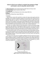
Báo cáo nghiên cứu khoa học: "Analysis of Early-age cracking in restrained ring specimens of high performance concrete using finite element method" pdf
... steel, using the command PLASTIC (although the behaviour of the steel ring was proved to be linear) Modeling of the ring test Finite element modeling of the ring specimens using ANSYS software ... strain In the finite element analysis the strain information was used as input using the assumption of a constrained radial displacement of the nodes of the outer circumference of the steel ring ... elements will start cracking as the stress in a particular layer exceeds the tensile strength of concrete (f’ t) The ring specimens The FEM of the ring test was performed using the software of...
Ngày tải lên: 21/07/2014, 17:21

Inverse analysis of dental implant systems using finite element method
... that changes of the biomechanical parameters of dental implant-bone systems have a pronounced effect on implant success Of all the means for studying this problem, finite element analysis (FEA) ... bone A stress analysis of effect of different types of restorative materials (Sevimay et al., 2005a) indicated that the use of more rigid or resilient material for the superstructure of an implant-supported ... presence of a bone defect of various shapes and dimensions The results of this analysis suggested that slight conical resorption might partially be the result of biomechanical adaptation of bone...
Ngày tải lên: 15/09/2015, 17:08

Modeling Of Wire On Tube Heat Exchangers Using Finite Element Method
... a Coil #5 Location of starting of phase change in tube # Location of starting of sub-cooling in tube # Location of starting of phase change in tube # Location of starting of sub-cooling in tube ... the analysis of wire-on-tube heat 420 G.A Quadir et al / Finite Elements in Analysis and Design 38 (2002) 417–434 Fig (a) One tube length of the wire-on-tube heat exchanger; (b) Bare portion of ... evaluation of cross ow compact heat exchangers using ÿnite elements, Int J Heat and Mass Transfer 32 (1989) 889–894 [11] S.G Ravikumar, K.N Seetharamu, P.A Aswatha Narayana, Finite element analysis of...
Ngày tải lên: 19/03/2016, 13:14

Bending And Vibration Analysis Of Multi-Folding Laminate Composite Plate Using Finite Element Method
... The element mass matrix given by ρ [Ni ]T [Ni ] dAe , [m]e = Ae with ρ is mass density of material (10) Bending and vibration analysis of multi-folding laminate composite plate using finite element ... and vibration analysis of multi-folding laminate composite plate using finite element method 195 3.2.2 Effect of folding angle on deflections In order to investigate the effect of folding angle ... shapes of folding angle α = 1200 for different boundary conditions The effect of folding angle on mode shapes Bending and vibration analysis of multi-folding laminate composite plate using finite element...
Ngày tải lên: 09/12/2016, 22:59

fundamentals of finite element analysis - hutton - (mcgraw-hill)
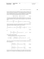
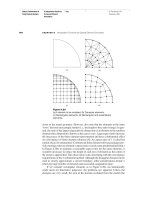
... total of 192 elements is shown Hutton: Fundamentals of Finite Element Analysis Basic Concepts of the Finite Element Method Text © The McGraw−Hill Companies, 2004 1.2 How Does the Finite Element ... Fundamentals of Finite Element Analysis Basic Concepts of the Finite Element Method Text © The McGraw−Hill Companies, 2004 1.2 How Does the Finite Element Method Work? 4.5 4.0 Exact Two elements Four elements ... Fundamentals of Finite Element Analysis Basic Concepts of the Finite Element Method Text 1.4 Brief History of the Finite Element Method compute additional, derived variables, such as reaction forces, element...
Ngày tải lên: 08/04/2014, 10:37
finite element analysis of pulsed
... are first conducted to verify the finite element analysis of melting and solidification Results of finite element analysis are compared with exact solutions of solidification and melting problems given ... for the elements involved in phase change are computed by the method of element removal and reactivation and the use of a new initial temperature at T s to calculate the stress/strain of the solidified ... 2.3 The Method of Element Removal and Reactivation In order to model the phenomena of melting and solidification, the element removal and reactivation method, ͓15͔, is applied An element will be...
Ngày tải lên: 06/05/2014, 08:55

Hutton book - fundametans of finite element analysis
... total of 192 elements is shown Hutton: Fundamentals of Finite Element Analysis Basic Concepts of the Finite Element Method Text © The McGraw−Hill Companies, 2004 1.2 How Does the Finite Element ... Fundamentals of Finite Element Analysis Basic Concepts of the Finite Element Method Text © The McGraw−Hill Companies, 2004 1.2 How Does the Finite Element Method Work? 4.5 4.0 Exact Two elements Four elements ... Fundamentals of Finite Element Analysis Basic Concepts of the Finite Element Method Text 1.4 Brief History of the Finite Element Method compute additional, derived variables, such as reaction forces, element...
Ngày tải lên: 26/05/2014, 03:41

finite element analysis of structural steelwork beam to column bolted connections 2001
... bending Table - Full Scale Test Results Finite Element Model MYSTRO and LUSAS FEA software was used for the finite element analysis The FEA models were created using command files rather than the ... modelled Figure - FEA Elements Element Types At the beginning of the research a number of trial models were created Models with fewer elements as well as models with only shell elements were tried ... design this reserve of capacity is of benefit to the Engineer In plastic design when members and connections are designed to yield this reserve of capacity has the effect of not allowing the...
Ngày tải lên: 04/06/2014, 13:20

SAP2000 - Three Dimensional Static and Dynamic Finite Element Analysis and Design of Structures
... Comprehensive Software for the Finite Element Modeling, Static, Dynamic and Non-Linear Analysis and Design of Structures Introduction Powerful and Integrated Structural Analysis and Desi gn Software ... model beams of variable sections Rigid End Offsets Frame Elements Rigid End connections to model large joints • SAP2000 • Automated end offset evaluation and assignment End Releases Frame Elements ... Shell Elements Powerful Shell Elements General quadrilateral or triangular element • SAP2000 • Isotropic, Orthotropic and Anisotropy material Powerful Shell Elements Shell Elements Six degrees of...
Ngày tải lên: 11/06/2014, 03:16

Finite Element Analysis: Thermomechanics of Solids doc
... 22 Finite Element Analysis: Thermomechanics of Solids Verify that T T (a) QQ = Q Q T −1 (b) Q = Q (c) For any × vector a Qa = a [The relation in (c) is general, and Qa represents a rotation of ... 2003 5:00 PM 36 Finite Element Analysis: Thermomechanics of Solids As proof, α j y j ⊗ βk zk = α j βk y j ⊗ zk = Ay j ⊗ Bz k = (A ⊗ B)(y j ⊗ z k ) (2.59) Now, the eigenvalues of A ⊗ In are × ... 4:55 PM 10 Finite Element Analysis: Thermomechanics of Solids It follows that vi = v ′ q ji , and hence j *M) v = Q T v ′ (a ) th v ′ = Qv ( b) (1.48) T in which qij is the ji entry of Q We can...
Ngày tải lên: 27/06/2014, 15:20
Báo cáo nghiên cứu khoa học: "COMPUTE AND DEFINE EXACTLY THE REGION OF ELASTIC REACTION FORCE FOR CALCULATING THE SECTION FORCE OF UNDERGROUND CONSTRUCTION BY FINITE ELEMENT METHOD" pptx
... - 2008 6.RESULT OF THE CALCULATION OF SECTION FORCE AND DEFINE THE REGION OF ELASTIC REACTION FORCE OF UNDERGROUND STRUCTURE 6.1.The receiving result of mesh 40 element : 30 elements beam on ... beam on the elastic foundation, 10 elements of normal 6.2.The receiving result of mesh 200 element : 154 elements beam on the elastic foundation, 46 elements of normal Bản quyền thuộc ĐHQG Trang ... STIFFNESS MATRIX OF THE BEAM ON THE ELASTIC FOUNDATION IN THE SYSTEM OF THE GLOBAL CO-ORDINATE In the above part, we presented the stiffness matrix with the system of local co-ordinate of element When...
Ngày tải lên: 22/07/2014, 03:20

Báo cáo nghiên cứu khoa học: "FINITE ELEMENT ANALYSIS OF ELASTO-PLASTIC BOUNDARY FOR SOME STRUCTURE PROBLEMS" pot
... 10x10=100 Fig Finite element idealisation of axisymmetric Fig Finite element idealisation of axisymmetric problem, mesh AM1 problem, mesh AM2 y p x 100mm 200mm Fig Finite element idealisation of plane ... Prof J F Debongnie, Lectures notes on Finite Element Method University of Liège, 1999 Trang 11 Science & Technology Development, Vol 9, No.8- 2006 [5] M A Crisfield, Non-Linear Finite Element Analysis ... Layer number 11 x 200 Uniform load q (KN/mm ) 20 Finite element idealisation: L ay e re d b e am cro ss-se ctio n Fig Finite element idealisation of meshes M1, M2, M3, M4, M5 Trang Science & Technology...
Ngày tải lên: 22/07/2014, 10:21

Fundamentals of Finite Element Analysis phần 1 pdf
... total of 192 elements is shown Hutton: Fundamentals of Finite Element Analysis Basic Concepts of the Finite Element Method Text © The McGraw−Hill Companies, 2004 1.2 How Does the Finite Element ... Fundamentals of Finite Element Analysis Basic Concepts of the Finite Element Method Text © The McGraw−Hill Companies, 2004 1.2 How Does the Finite Element Method Work? 4.5 4.0 Exact Two elements Four elements ... Fundamentals of Finite Element Analysis Basic Concepts of the Finite Element Method Text 1.4 Brief History of the Finite Element Method compute additional, derived variables, such as reaction forces, element...
Ngày tải lên: 08/08/2014, 17:20

Fundamentals of Finite Element Analysis phần 2 pps
... length of each element and the direction cosines of element orientation Table 3.2 Element- Node Connectivity Table for Figure 3.2 Node Element i j 2 3 Hutton: Fundamentals of Finite Element Analysis ... modulus of elasticity of the element material 3.4 DIRECT ASSEMBLY OF GLOBAL STIFFNESS MATRIX Having addressed the procedure of transforming the element characteristics of the one-dimensional bar element ... Specification of the cross-sectional area A and modulus of elasticity E of each element allows computation of the element stiffness matrix in the global frame using Equation 3.28 Finally, the element...
Ngày tải lên: 08/08/2014, 17:20
Fundamentals of Finite Element Analysis phần 3 pps
... displacements, inclusion of beam element nodal rotations ensures compatibility of rotations at nodal connections between Hutton: Fundamentals of Finite Element Analysis Flexure Elements Text © The McGraw−Hill ... same as those of elementary beam theory with the addition of The element is of length L and has two nodes, one at each end The element is connected to other elements only at the nodes Element loading ... Hutton: Fundamentals of Finite Element Analysis Flexure Elements Text © The McGraw−Hill Companies, 2004 4.4 Flexure Element Stiffness Matrix where V is total volume of the element Substituting...
Ngày tải lên: 08/08/2014, 17:20
Fundamentals of Finite Element Analysis phần 4 pps
... integration of various forms of the interpolation functions over the domain of an element are Hutton: Fundamentals of Finite Element Analysis Interpolation Functions for General Element Formulation ... to the beam element begins with consideration of the equilibrium conditions of a differential section taken along the 149 Hutton: Fundamentals of Finite Element Analysis 150 Method of Weighted ... Fundamentals of Finite Element Analysis Method of Weighted Residuals Text © The McGraw−Hill Companies, 2004 5.4 Application of Galerkin’s Method to Structural Elements Galerkin’s finite element method...
Ngày tải lên: 08/08/2014, 17:20
Fundamentals of Finite Element Analysis phần 5 docx
... equation of the line passing through nodes and strictly by geometry, using the equation of a two-dimensional straight line y = m x + b Using the Hutton: Fundamentals of Finite Element Analysis ... Burnett, D S Finite Element Analysis Reading, MA: Addison-Wesley, 1987 Zienkiewicz, O C The Finite Element Method, 3rd ed London: McGraw-Hill, 1977 Stasa, F L Applied Finite Element Analysis for ... if the finite element model of the problem is composed of M elements, one boundary condition is imposed at node of element and the second boundary condition is imposed at node of element M The...
Ngày tải lên: 08/08/2014, 17:20

Fundamentals of Finite Element Analysis phần 6 pptx
... Example 7.5: (a) Two-dimensional fin (b) Finite element model (c) Element edge convection (d) Element edge convection Hutton: Fundamentals of Finite Element Analysis Applications in Heat Transfer ... (a) ؒ m (b) Figure 7.16 (a) Oil cooler tube of Example 7.9 (b) Element and node numbers for a four -element model Hutton: Fundamentals of Finite Element Analysis Applications in Heat Transfer Text ... What of the element surface areas that are part of the surface area of the volume being modeled? Generally, these outside areas are subjected to convection 269 Hutton: Fundamentals of Finite Element...
Ngày tải lên: 08/08/2014, 17:20