modeling and position control of mobile robot
modeling and motion control of mobile robot for lattice type welding
... DOF of the mobile robot is three Yang Bae Jeon, Sang Bong Kim and Soon Sil Park 88 because of added freedom of the torch slider For the number of actuator inputs is equal to the DOF of the mobile ... position of the mobile robot must be controlled to asymptotically converge because of a limited length of torch slider In addition, a slider of the mobile robot carrying torch must be controlled ... Proceedings of the 1999 American Control Conference, pp 2435 -2439 dAndrea-Novel, B., Bastine, G., and Campion, G., 1991, "Modelling and Control of Nonholonornic Wheeled Mobile Robots," Proceedings of
Ngày tải lên: 26/10/2014, 14:38

Kinematic and dynamic analysis of mobile robot
... for our project 2.2 Kinematic and Dynamic Modeling of Mobile Robot In the literature of mobile robot, kinematic and dynamic modeling of WMR can be classified under two ... review of existing kinematic and dynamic models of mobile robot Chapter 3 is one of the two main chapters of thesis We will first be presenting the kinematic modeling of mobile ... four wheels mobile robot 35 3.13 Simulation of four wheels mobile robot with applied velocity in y direction 37 3.14 Initial and final position of four wheels mobile robot
Ngày tải lên: 08/11/2015, 17:24

REPORT TOPIC MODELING AND SIMULATING THE THREEWHEELED MOBILE ROBOT
... UNIVERSITY OF SCIENCE AND TECHNOLOGY SCHOOL OF ELECTRICAL - ELECTRONICS FACULTY OF AUTOMATON *** REPORT TOPIC: MODELING AND SIMULATING THE THREEWHEELED MOBILE ROBOT INSTRUCTOR: ... robot is a mobile robot is a mobile robot whose movement is based on separately driven wheels placed on their side of the robot body It can change its direction by varying the relative rate of ... kinematic controller affect a lot of to the system, the WMR’s trajectory will changes very much comparing with effect of dynamic controller Reference [1] WHEELED MOBILE ROBOTICS, Gregor Klancar, Andrej
Ngày tải lên: 05/08/2022, 04:12

REPORT TOPIC MODELING AND SIMULATING THE THREEWHEELED MOBILE ROBOT
... Škrjanc [2] Mobile robot, 2016, https://en.wikipedia.org/wiki /Mobile_ robot (accessed 18.07.16) [3]“Design and implementation of an adaptive sliding-mode dynamic controller for wheeled mobile robots”, ... robot is a mobile robot is a mobile robot whose movement is based on separately driven wheels placed on their side of the robot body It can change its direction by varying the relative rate of ... UNIVERSITY OF SCIENCE AND TECHNOLOGY SCHOOL OF ELECTRICAL - ELECTRONICS FACULTY OF AUTOMATON *** REPORT TOPIC: MODELING AND SIMULATING THE THREEWHEELED MOBILE ROBOT INSTRUCTOR:
Ngày tải lên: 05/08/2022, 10:17

modeling and optimal control of atmospheric pollution hazard in nuclear and chemical disasters
... and amount of emergency respond forces, the handling of hazardous sources, the area and means of evacuation, the area of guard regions, the area of decontamination, etc The effects and cost of ... Cybernetics theory, effective and economic cost evaluation of control techniques, and optimization methods Some applications and illustrations of modeling and optimal control are reported byby Elsevier ... the basis of modeling, theories and technologies for controlling nuclear and chemical disaster hazard need to be developed The control of hazard has two aspects: the prevention of risk and the
Ngày tải lên: 02/11/2022, 14:35

(TIỂU LUẬN) REPORT TOPIC MODELING AND SIMULATING THE THREEWHEELED MOBILE ROBOT
... Škrjanc [2] Mobile robot, 2016, https://en.wikipedia.org/wiki /Mobile_ robot (accessed 18.07.16) [3] “Design and implementation of an adaptive sliding-mode dynamic controller for wheeled mobile robots”, ... robot is a mobile robot is a mobile robot whose movement is based on separately driven wheels placed on their side of the robot body It can change its direction by varying the relative rate of ... UNIVERSITY OF SCIENCE AND TECHNOLOGY SCHOOL OF ELECTRICAL - ELECTRONICS FACULTY OF AUTOMATON *** REPORT TOPIC: MODELING AND SIMULATING THE THREEWHEELED MOBILE ROBOT INSTRUCTOR:
Ngày tải lên: 13/12/2022, 06:49
Control of Redundant Robot Manipulators - R.V. Patel and F. Shadpey Part 10 docx
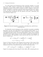
... position and force controlled axes were used (see Figure 5.4). Figure 5.3 Desired impedance a) position controlled axis, and b) force- controlled axis To check the correct operation of the controller ... each of the 6 DOF’s of the {C} frame. Figure 5.3 shows the desired impedance in position- controlled and force-controlled axes respec- tively. I n order to verify the operation of the AHIC scheme, ... the responses of the two systems. The impedance values used for this test in all 6 DOF’s of the {C} frame were Figure 5.5 shows the plots of the changes in the position of the origin of the frame
Ngày tải lên: 10/08/2014, 01:22

Control of Redundant Robot Manipulators - R.V. Patel and F. Shadpey Part 11 doc
... performance of the proposed AHIC scheme for compliant motion and force control of REDIESTRO Considering the complexity and the large amount of calculations involved in force and compliant motion control ... experimental results for force and compliant motion control of a 7-DOF manipulator have been reported In [67], a set of experiments on contact force control carried out on a 7-DOF Robotics Research Corporation ... for force and compliant motion control 6.2 6.2.1 Preparation and Conduct of the Experiments Selection of Desired Impedances The desired equation of motion in a position (impedance)-controlled
Ngày tải lên: 10/08/2014, 01:22

Control of Redundant Robot Manipulators - R.V. Patel and F. Shadpey Part 12 pdf
... Numerical values of the desired impedances (Strawman Task II) Position- controlled axis Force-controlled... head of the peg and the top of the holes facilitate the correct initiation of the insertion ... performance of the controller and its robustness with respect to kinematic e rrors. As an example, the design of the peg and holes (cone-shaped peg heads and chamfered type opening at the top of the ... desired masses for the position and the force-controlled directions are and respectively. The values of the desired damping in the position and the force-controlled directions are 0 5 10
Ngày tải lên: 10/08/2014, 01:22

Control of Redundant Robot Manipulators - R.V. Patel and F. Shadpey Part 13 pps
... performance of the AHIC scheme in compliant motion and force control of REDIESTRO Considering the complexity and the computation involved in force and compliant motion control of a 7-DOF redundant ... time-controlled schedule By starting segment 5, all axes come under position control so as to position the 174 Experimental Results for Contact Force and Compliant Motion Control peg on top of ... part of the controller, and even friction compensation is not required The modified AHIC scheme increases the applicability of this type of control to a large class of industrial and research
Ngày tải lên: 10/08/2014, 01:22

Neural network adaptive force and motion control of robot manipulators in the operational space formulation
... FORCE AND MOTION CONTROL OF ROBOT MANIPULATORS IN THE OPERATIONAL SPACE FORMULATION DANDY BARATA SOEWANDITO (MSME, New Jersey Inst of Technology) A THESIS SUBMITTED FOR THE DEGREE OF DOCTOR OF PHILOSOPHY ... consists of translational and rotational motions, therefore, F∗ motion consists of two types of control forces: one is force control to control translational motion and the other one is moment control ... to come Also to Assoc Prof Zhiming ”Jimmy” Ji and Prof Ian S Fischer of New Jersey Inst of Tech (NJIT), who taught me robotics and dual-number kinematics, respectively And also to my former college
Ngày tải lên: 14/09/2015, 08:50

Summary of the doctoral thesis: Inverse dynamics and motion control of delta parallel robot
... Research objects: Dynamics? ?and? ?control? ?of? ?two Delta parallel robots are 3RUS robots? ?and? ?3PUS robots. The main content of? ? the thesis includes: Study of? ? mathematical and? ? mechanical modeling? ? problems, ... equations of motion of robot models From the equation? ?of? ?motion? ?of? ?model 1? ?and? ?model 2? ?of? ?each? ?robot? ?we have the comparison table as follows: 8 Table 2.1 Compare the equations? ?of? ?motion? ?of? ?Models 1? ?and? ?2 ... simulation of inverse kinematics and inverse dynamics of Delta parllel robot 3.3.1 Numerical simulation of 3RUS inverse kinematics of robot To evaluate the correctness? ?of? ?algorithms? ?and? ?calculations? ?of? ?the thesis,
Ngày tải lên: 09/01/2020, 14:17

Summary of the doctoral thesis: Inverse dynamics and motion control of delta parallel robot
... Research objects: Dynamics? ?and? ?control? ?of? ?two Delta parallel robots are 3RUS robots? ?and? ?3PUS robots. The main content of? ? the thesis includes: Study of? ? mathematical and? ? mechanical modeling? ? problems, ... equations of motion of robot models From the equation? ?of? ?motion? ?of? ?model 1? ?and? ?model 2? ?of? ?each? ?robot? ?we have the comparison table as follows: 8 Table 2.1 Compare the equations? ?of? ?motion? ?of? ?Models 1? ?and? ?2 ... simulation of inverse kinematics and inverse dynamics of Delta parllel robot 3.3.1 Numerical simulation of 3RUS inverse kinematics of robot To evaluate the correctness? ?of? ?algorithms? ?and? ?calculations? ?of? ?the thesis,
Ngày tải lên: 13/01/2020, 23:01
Modelling and Control of Snake Robots
... modelling and control of snake robots as steps toward developing snake robots capable of such operations. A survey of the various mathematical models and motion patterns for snake robots found ... development of model- based controllers for snake robots. Some controllers are developed for po- sition control of a single link or a small selection of snake robot links. Moreover, controllers ... Type of joints, 2) number of degrees of freedom (DOF) and 3) with or without passive caster wheels. Most snake robots consist of links connected by revolute joints with one or two DOF. On some robots,...
Ngày tải lên: 04/08/2014, 09:37

Control of Redundant Robot Manipulators - R.V. Patel and F. Shadpey Part 1 pptx
... the position and force control of redundant robot manipulators from both theoretical and experimental points of view. Although position and force control of robot manipulators has been an area of ... Results for a 3-DOF Planar Arm . . . 94 CHAPTER 1INTRODUCTION The problem of position control of robot manipulators was addressed in the 1970’s to develop control schemes capable of controlling a ... the point of view of experimental implementation. Most of the experimental work done to illustrate algorithms for force and position control of redun- dant manipulators has been based on planar 3-DOF...
Ngày tải lên: 10/08/2014, 01:22
Control of Redundant Robot Manipulators - R.V. Patel and F. Shadpey Part 2 ppsx
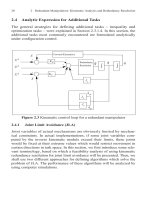
... kinematic control loop for Carte- sian control of a redundant manipulator (Figure 2.3). As we can see in Fig- ure 2.3, the states of the system are and . However, because of the nature of Cartesian control ... matrix, and being the and Jacobian matrices of the main and additional tasks respectively. The velocity kinematics of the extended task are given by: (2.3.9) where and are the time derivatives of ... than the dimension of the joint space n. Let us denote the position and orientation of the end-effector along the axes of interest in a fixed frame by the vector X , and the joint positions by thevector...
Ngày tải lên: 10/08/2014, 01:22
Control of Redundant Robot Manipulators - R.V. Patel and F. Shadpey Part 3 pot
... Tasks21 2.4.1.1 Definition of Terms and Feasibility Analysis The reachable workspace of a robot manipulator is defined by the geo- metrical locus of the position and orientation (pose) of the end-effector, , ... major areas: redundancy resolution, robot and environment modeling, and dis- tance calculation need to be investigated. Obviously, the accuracy with which a robot arm and its environment are modeled ... Static and Moving Obstacle Collision Avoidance In this section, an outline of an algorithm for the 2-D workspace of a planar arm is given. The extension of the algorithm to a 3-D workspace and simulation...
Ngày tải lên: 10/08/2014, 01:22
Control of Redundant Robot Manipulators - R.V. Patel and F. Shadpey Part 4 pptx
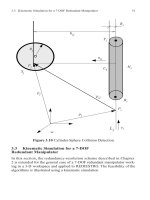
... and of the cylinder onto the line and denote the projected points by and . Con- versely, we project the points and of the cylinder onto the line and denote the projected points by and ... passes through the points and of and (with and being the closest points of the two lines to the origin), then the dual rep- resentation of is given as b i b' i t i andb' i b i – R i R j + b i t' i t i andt' i t i – ... Collision Avoidance 39 the foot of the common normal of the two lines and on . To avoid ambiguity for the choice of the top and bottom of the cylinder, we can always choose and in such away that the...
Ngày tải lên: 10/08/2014, 01:22
Control of Redundant Robot Manipulators - R.V. Patel and F. Shadpey Part 5 pptx
... unit vector along the Z axis of joint i ,is the position of the end-effector, andis the position of the origin of the ith frame with respect to frame {1} . The position and the velocity errors are ... pose (position and orientation) of the end-effector, defined by the position vector and the rotation matrix of the transformation matrix . The pose is thus dimensionally non-homogenous and needs ... Si mul ati on for a 7-DOF Redun dant Manipulator 53 (3.3.1) where ;,,, and are the twist angle, joint angle, offset and link length, respectively. The Denavit-Hartenberg parameters of REDI- ESTRO are...
Ngày tải lên: 10/08/2014, 01:22
Bạn có muốn tìm thêm với từ khóa:
- online estimation and adaptive control of bioreactors pdf
- online estimation and adaptive control of bioreactors
- estimation and adaptive control of bioreactors
- robust recurrent neural network control of biped robot
- modeling of mobile robot
- bastin dochain online estimation and adaptive control of bioreactors