list 3 input and output devices


Input and output of dissolved organic and inorganic nitrogen in subtropical forests of South China under high air pollution docx
Ngày tải lên: 23/03/2014, 00:20


Mechanisms and Mechanical Devices Sourcebook - Chapter 3
... photoemitter and photoreceiver. Sclater Chapter 3 5 /3/ 01 10: 23 AM Page 90 64 Sclater Chapter 3 5 /3/ 01 10:20 AM Page 64 81 Fig. 19 A paste belt applicator passes around the pulley in a pastepot and slides ... shaft. Sclater Chapter 3 5 /3/ 01 10:22 AM Page 87 66 Fig. 3 In another type of action, the forward and return strokes are accomplished by a suitable mechanism, while the raising and lowering is imparted ... line. This will cause the bobbin changer to operate. Sclater Chapter 3 5 /3/ 01 10:22 AM Page 86 91 Sclater Chapter 3 5 /3/ 01 10: 23 AM Page 91 Fig. 4 Control for the automatic shear. When a seam of...
Ngày tải lên: 22/10/2012, 14:26

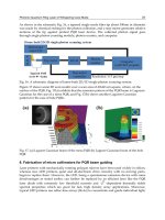

Cấu trúc máy tính và lập trình Assembly : Input /Output Devices part 10 ppsx
Ngày tải lên: 26/07/2014, 17:20



IELTS Part 2 and Part 3 Topics and Questions
... What do you think was the best part of this film? Part 3 See also the Part 3 questions for Topic #6, 'A Film' and the Part 3 questions for Topic #99 'A Type of Film'. Films ... ******************************************************* **************** IELTS Part 2 and Part 3 Topics and Questions Page 30 146. A Family 147. Your Work or Study Place 148. A Recent Change (2) 149. ... some of the advantages and some of the disadvantages of big and of small families? • Compare the advantages and disadvantages of family planning. • What are the advantages and disadvantages of...
Ngày tải lên: 05/10/2012, 11:54

Mechanisms and Mechanical Devices Sourcebook - Chapter 4
... shown, S = 1. From the geometry, ( θ 30 + ∆ θ 30 )L 3 = 36 0º and S = ∆ θ 3 / θ 30 Hence θ 30 (1 + S)L 3 = 36 0º For S = 1 and L 3 + 2, θ 30 = 90º and ∆ θ 3 = 90º Now select a convenient profile ... 3 must mesh with every lobe on gear 4, and T 3 /T 4 = L 3 /L 4 = 2 /3, where T 3 and T 4 are the numbers of teeth on gears 3 and 4. T 1 and T 2 will denote the numbers of teeth on gears 1 and ... number of lobes L 3 and L 4 on the gears 3 and 4. In the drawings, L 3 = 2 and L 4 = 3. Any two lobes on the two gears (i.e., any two lobes of which one is on one gear and the other on the...
Ngày tải lên: 22/10/2012, 14:26

Mechanisms and Mechanical Devices Sourcebook - Chapter 5
... 5 5 /3/ 01 11:45 AM Page 138 134 TWELVE EXPANDING AND CONTRACTING DEVICES Parallel bars, telescoping slides, and other devices that can spark answers to many design problems. Fig. 1 Figs. 1 and ... continuous rotary input motion into an output that oscillates the shaft back and forth. Sclater Chapter 5 5 /3/ 01 11:47 AM Page 170 inputs, and z is the output. The motion of x and y in the same ... motion of an input crank into a much larger rotation of the output (from 30 º to 36 0º). The crank drives the slider and gear rack, which in turn rotates the output gear. 1 53 Springs and chains are...
Ngày tải lên: 22/10/2012, 14:26

Mechanisms and Mechanical Devices Sourcebook - Chapter 6
... their seats. Sclater Chapter 6 5 /3/ 01 12:25 PM Page 191 CHAPTER 6 SPRING, BELLOW, FLEXURE, SCREW, AND BALL DEVICES Sclater Chapter 6 5 /3/ 01 12:24 PM Page 1 73 installed and integrated into a design ... screw thread and a notched ear or a bent wire as the nut. DOUBLE THREADING Sclater Chapter 6 5 /3/ 01 12:25 PM Page 1 93 196 FOURTEEN ADJUSTING DEVICES Here is a selection of some basic devices that ... spring is wound to the desired torque. Figs 13 and 14 Rack and toothed stops (Fig. 13) are frequently used to adjust heavy louvers, boiler doors and similar equipment. The adjustment is not continuous;...
Ngày tải lên: 22/10/2012, 14:26

Mechanisms and Mechanical Devices Sourcebook - Chapter 7
... motor, the maximum output speed will be 1200 = 39 84 rpm, and the minimum output speed = 39 84/11 = 36 2 rpm. Double-reduction system (Fig. 3) . Solid sheaves are on both the input and output shafts, ... Chapter 7 5 /3/ 01 12 :34 PM Page 235 232 BUSHED ROLLER CHAINS AND THEIR ADAPTATIONS Various roller, side-plate and pin configurations for power transmissions, conveying, and elevating. STANDARD ROLLER ... voltage, varies output speed. Sclater Chapter 7 5 /3/ 01 12 :33 PM Page 2 23 227 GETTING IN STEP WITH HYBRID BELTS Imaginative fusions of belts, cables, gears and chains are expanding the horizons...
Ngày tải lên: 22/10/2012, 14:26
Mechanisms and Mechanical Devices Sourcebook - Chapter 8
... stator, which trans- mits the reaction forces to the housing. * Four U.S. patents (3, 094,880, 3, 139 ,771, 3, 139 ,772, and 3, 590,659) have been issued to A. M. Maroth. A variable-speed-transmission cone ... one side for 30 , 35 , or 60 min. The recorders included a motor com- parable in size and power to those used in standard reel-to-reel recorders, and a large bi-peripheral flywheel and sturdy capstan ... gears f and d mounted on output shaft b. Spur gear c meshes with idler e and with spur gear d. Idler e meshes with spur gears c and f. The output shaft b carries two free-wheel disks g and h,...
Ngày tải lên: 22/10/2012, 14:26

Mechanisms and Mechanical Devices Sourcebook - Chapter 9
... Chapter 9 5 /3/ 01 12:57 PM Page 31 7 33 6 LINKAGES FOR BAND CLUTCHES AND BRAKES Fig. 1 An outside band clutch operated by a roller and cone. Fig. 2 An outside band clutch made as two half wrap bands with ... 9. C T n 1 /3 0 .3 x=1 x=n l x S S ∑ −− 11 2 () bd TE C n 2 2 e 0 .3 13/ σ n T 0.7 1 /3 bd TE 2 2 13/ T E 13/ dT bE 13/ Ebt dn 3 09. Critical ... clutches are on the input gears in this drive. These also give smooth output speed and little output lag as the direction changes. Sclater Chapter 9 5 /3/ 01 12:57 PM Page 31 3 32 6 TWELVE APPLICATIONS...
Ngày tải lên: 22/10/2012, 14:26

Mechanisms and Mechanical Devices Sourcebook - Chapter 10
... Chapter 10 5 /3/ 01 1:07 PM Page 35 1 36 0 Limit Switches in Machinery (continued ) Sclater Chapter 10 5 /3/ 01 1:08 PM Page 36 0 35 2 DRIVES FOR CONTROLLING TENSION Mechanical, electrical, and hydraulic ... and fluid velocities for their actuation. 36 2 Fig. 1 Auxiliary piston governor. Fig. 2 Hit -and- miss governor. Fig. 3 Force-compensated regulator. Sclater Chapter 10 5 /3/ 01 1:08 PM Page 36 2 34 5 Fig. ... engines, and small steam turbines. 36 5 Sclater Chapter 10 5 /3/ 01 1:08 PM Page 36 5 LIMITERS PREVENT OVERLOADING These 13 “safety valves” give way if machinery jams, thus preventing serious damage. 34 3 Fig....
Ngày tải lên: 22/10/2012, 14:26
Mechanisms and Mechanical Devices Sourcebook - Chapter 11
... instantly. Sclater Chapter 11 5 /3/ 01 1:17 PM Page 4 03 3 83 Gaging and callipering. The thickness of a moving wire or strip is gaged by the position of the floating spool and transformer core. If the ... Chapter 11 5 /3/ 01 1:16 PM Page 39 2 402 INSTANT MUSCLE WITH PYROTECHNIC POWER Cartridge-actuated devices generate a punch that cuts cable and pipe, shears bolts for fast release, and provides ... is 20 to 270°F, and its accuracy is ±1°F. The maximum pressure rating is 100 psi for dead-end service and 200 psi for continuous flow. Sclater Chapter 11 5 /3/ 01 1:17 PM Page 39 6 37 7 (Note: In place...
Ngày tải lên: 22/10/2012, 14:26

Mechanisms and Mechanical Devices Sourcebook - Chapter 13
... φ 13 , with ψ 12 , and ψ 14 . Fig. 2 Three angular positions, φ 12 , φ 13 , φ 14 , are synchronized by four-bar linkage here with ψ 12 , ψ 13 , and ψ 14 . Sclater Chapter 13 5 /3/ 01 1 :33 ... establishes points A′ 2 , A′ 3 and A′ 4 , but here A′ 3 and A′ 4 coincide because of symmetry of A 3 and A 4 about A 0 B 0 . 4. Draw lines A 1 A′ 2 and A 1 A′ 4 , and the perpendicular bisectors of ... acceleration of the driven member. 438 Sclater Chapter 13 5 /3/ 01 1 :32 PM Page 438 the output velocity at crank angle θ = 60º can be computed as follows: L/R = 12/4 = 3 From Fig. 3 β′ / ω = 0.175 β′ = 0.175(1000)...
Ngày tải lên: 22/10/2012, 14:26

Mechanisms and Mechanical Devices Sourcebook - Chapter 14
... organic and freeform shapes. Consequently, commercial software producers offer 3D hybrid surface and solid-modeling suites that integrate 2D drafting and 3D wireframe with 3D surface and 3D solid ... in commercial CAD software include • 2D drafting • 3D wireframe and surface modeling • 3D solid modeling • 3D feature-based solid modeling • 3D hybrid surface and solid modeling Two-Dimensional Drafting Two-dimensional ... discovery of the principles of 3D isometric and perspec- tive drawing in the Middle Ages resulted in a more realistic and accurate portrayal of objects than 2D drawings, and they con- veyed at a glance...
Ngày tải lên: 22/10/2012, 14:26