learning autocad electrical 2010 iec volume 1 slipstream

Tiêu chuẩn Quốc gia TCVN 7590-1:2010 - IEC 61347-1:2007
... TCVN 7590 (IEC 613 47) có tiêu chuẩn sau: 1) TCVN 7590 -1 :2 010 (IEC 613 47 -1: 2007), Bộ điều khiển bóng đèn – Phần 1: Yêu cầu chung yêu cầu an toàn 2) TCVN 7590-2 -1: 2007 (IEC 613 47-2 -1: 2006), Bộ ... TCVN 7590 -1 :2 010 IEC 613 47 -1: 2007 BỘ ĐIỀU KHIỂN BÓNG ĐÈN – PHẦN 1: YÊU CẦU CHUNG VÀ YÊU CẦU AN TOÀN Lamp controlgear – Part 1: General and safety requirements Lời nói đầu TCVN 7590 -1 :2 010 thay ... chuẩn phải đo chọn TCVN 6479 (IEC 609 21) có đặc điểm qui định tờ liệu bóng đèn tương ứng nêu TCVN 7670 (IEC 600 81) TCVN 7863 (IEC 609 01) H .11 Điều kiện thử nghiệm H .11 .1 Thời gian trễ đo điện trở
Ngày tải lên: 07/02/2020, 03:21

Tiêu chuẩn Quốc gia TCVN 8098-1:2010 - IEC 60051-1:1997
... hiệu 10 18 E 15 P T dexiben dB peta 10 héc Hz teta 10 12 ôm giây s (chữ thường) giga 10 mega 10 6 G M (chữ hoa) k (chữ thường) siemens S (chữ hoa) kilo 10 tesla T héctô 1) 10 2 h (chữ thường) 10 da ... B -1 … B -10 ); g) (các) ký hiệu E -1 … E -10 ); p) (ký hiệu D -1 … D-6); r) bị hủy; z) (ký hiệu F-33 số thông tin cần thiết khác cho tài liệu riêng) aa) (ký hiệu theo IEC 610 10 -1, sửa đổi 2, Mục 5 .1. 5) ... analogue electrical measuring instruments and their accessories - Part 1: Definitions and general requirements common to all parts Lời nói đầu TCVN 8098 -1 :2 010 hoàn toàn tương đương với IEC 600 51- 1 :19 97;
Ngày tải lên: 08/02/2020, 04:18

Tiêu chuẩn Quốc gia TCVN 7417-1:2010 - IEC 61386-1:2008
... TCVN 7 417 -1 :2 010 thay TCVN 7 417 -1: 2004; TCVN 7 417 -1 :2 010 hoàn toàn tương đương với IEC 613 86 -1: 2008; TCVN 7 417 -1 :2 010 Tiểu Ban kỹ thuật tiêu chuẩn quốc gia TCVN/TC/E4/SC1 Dây cáp có bọc cách điện ... TCVN 7 417 -1 :2 010 IEC 613 86 -1: 2008 HỆ THỐNG ỐNG DÙNG CHO LẮP ĐẶT CÁP - PHẦN 1: YÊU CẦU CHUNG Conduit systems for cable management- Part 1: General requirements Lời nói đầu TCVN 7 417 -1 :2 010 thay ... nêu 14 .1. 1 14 .1. 2 14 .1. 2 Cấp bảo vệ chống xâm nhập vật rắn 14 .1. 2 .1 Cụm lắp ráp gồm ống phụ kiện ống thực cách sử dụng tất lối vào ống Nếu cần, đầu để hở cụm nút lại, không phận thử nghiệm 14 .1. 2.2
Ngày tải lên: 08/02/2020, 16:32

Learning AutoCAD 2010, Volume 1 phần 3 docx
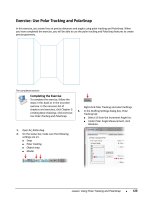
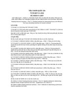
... marker should appear (1) , indicating the snap point Click to select the point Lesson: Using Object Snaps s 10 9 3 SHIFT+right-click and select the object... Object Snaps s 11 1 Practice Exercise: ... Part 1 In this part of the exercise, you begin to draw the front view of the bracket, beginning at point (1) and ending at point (2) Then, you resume drawing from point (1) to point (3) 1 Open ... Drag the cursor upward making sure that the angle field displays 90 degrees s Enter 10 0 Press ENTER s 9 11 To draw a line and correct a mistake using the Undo command: s Drag the cursor to
Ngày tải lên: 09/08/2014, 11:20
Learning AutoCAD 2010, Volume 1 phần 4 docx
... 51 mm thick 4 Save and close all files Challenge Exercise: Architectural s 15 1 Imperial Units 1 2 15 2 Open I_ARCH-Challenge-CHP02.dwg Draw... unit setting s AutoCAD is accurate 14 ... and to the right s Enter 2 '4 -1/ 4 Press... s Move the cursor to the left s Enter 15 '-3" Press TAB s Enter 18 0 Press TAB s Click anywhere in the drawing 10 For the next point: s Move the ... Click anywhere in the drawing 11 For the next point: s Move the cursor to the left s Enter 44 '-5" Press TAB s Enter 18 0 Press TAB s Click anywhere in the drawing 12 Right-click and click Close,
Ngày tải lên: 09/08/2014, 11:20

Learning AutoCAD 2010, Volume 1 phần 9 pot
... Boundaries s 3 71 10 To remove the construction lines: s Start the Erase command s Select the lines indicated in the following image Press ENTER 11 Your completed drawing 12 Close all files ... command 11 Using the Trim command, clean up the hidden lines as shown in the following image 13 To offset another line: s When prompted for... offset, select the centerline again (1) s When ... shorten objects to cutting edges. 1. On the ribbon, click Home tab > Modify panel > Trim. 2. Either select the objects to serve as cutting edges (1) and then press ENTER, or press
Ngày tải lên: 09/08/2014, 11:20
Learning AutoCAD 2010, Volume 1 phần 10 pot
... Lesson: Changing Part of an Object's Shape s 4 31 11 To select a... fillet should appear as shown Lesson: Applying a Radius Corner to Two Objects s 411 11 To complete the right view: s Press ENTER ... already been applied in this image 10 Select the edges on the opposite side of the view 11 Use Zoom and Pan to display the... Architectural s 433 3 4 434 Add a 915 mm door opening in the right ... ■ 403 10 . To move this object to the Hidden2 layer: ■ On the Layers panel, click the Layers list. ■ Click the Hidden2 layer to move the selected object to this layer. 11 . Press
Ngày tải lên: 09/08/2014, 11:20

Learning AutoCAD 2010, Volume 2 phần 4 potx
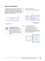
... ■ 11 1 11 2 ■ Chapter 8: Dimensioning Practice Exercise: Jogged Radius Dimensions In this practice exercise you draw an arc and use the Jogged radius dimension command. 1. ... s 11 9 1 2 3 12 0 Enter UCS... Select the left end extension line 1 and 2 as shown s Right-click Click Break The selected extension lines break whenever they cross another extension line 13 ... steps give an overview for breaking dimensions: 1 Start the Dimbreak command Lesson: Creating Dimensions s 12 1 2 Select the dimension to break (1) Note: Use the Multiple option to break multiple
Ngày tải lên: 09/08/2014, 11:20
Learning AutoCAD 2010, Volume 2 phần 6 pptx
... Click OK 20 2 s Chapter 9: Hatching Objects 13 On the Layers panel, freeze the Hatch_Swatch layer 14 On the Layers panel, thaw the BackgroundFrame layer 15 Zoom to display the entire drawing Note: ... a single hatch object 9 Zoom to display the entire drawing 19 8 s Chapter 9: Hatching Objects 15 Zoom to display your entire drawing 16 . .. the scale of a hatch object or as complex as altering ... select AR-B 816 C from the Pattern list s In the Scale field, enter 1 s Place a check mark in the box next to the Create Separate Hatches option s Click Add: Pick Points s Click two points (1) and (2)
Ngày tải lên: 09/08/2014, 11:20

Learning AutoCAD 2010, Volume 2 phần 7 docx
... hatch and gradient fills that have been placed in the drawing. 218 ■ Chapter 9: Hatching Objects Chapter Overview ■ 219 Chapter 10 Working with Reusable Content When you create a drawing ... refer to the "Settings for the Exercises" section in the Introduction in Volume 1. 220 ■ Chapter 10 : Working with Reusable Content Lesson: Using Blocks This lesson describes how ... Architectural symbols 222 ■ Chapter 10 : Working with Reusable Content The following illustration shows an example of typical blocks you might use to create a mechanical or electrical drawing.
Ngày tải lên: 09/08/2014, 11:20

Learning AutoCAD 2010, Volume 2 phần 8 pptx
... content. Warning! If completing this exercise with AutoCAD LT, in step 3, you will need to locate the block at \Program Files \AutoCAD LT 2 010 \ Sample\DesignCenter\Fasteners - Metric.dwg. ... refer to the "Settings for the Exercises" section in the Introduction in Volume 1. 260 ■ Chapter 11 : Creating Additional Drawing Objects Lesson: Working with Polylines This lesson ... challenge exercise. 256 ■ Chapter 10 : Working with Reusable Content 3. Insert the block Hex Flange Screw - 10 mm top from the file \Program Files \AutoCAD 2009\Sample \DesignCenter\Fasteners
Ngày tải lên: 09/08/2014, 11:20

Learning AutoCAD 2010, Volume 2 phần 9 doc
... following Room Schedule data: s NUMBER - NAME - AREA s 22 1 - SLEEPING QUARTERS - 21 m2 s 20 1 - READY ROOM - 36 m2 s 20 2 - LOCKER ROOM - 14 m2 s 20 3 - EXERCISE ROOM - 23 m2 s 20 5 - DINING ... 20 6 - KITCHEN - 6 m2 s 20 7 - MEN'S TOILET ROOM - 11 m2 s 20 8 - WOMEN'S TOILET ROOM - 14 m2 7 Save and close the drawing Imperial Units 1 2 3 Open the drawing you saved from the previous ... NAME - AREA s 22 1 - SLEEPING QUARTERS - 23 6 SQ/FT s 20 1 - READY ROOM - 386 SQ/FT s 20 2 - LOCKER ROOM - 15 0 SQ/FT s 20 3 - EXERCISE ROOM - 383 SQ/FT s 20 5 - DINING ROOM - 13 4 SQ/FT s 20
Ngày tải lên: 09/08/2014, 11:20

Learning AutoCAD 2010, Volume 2 phần 10 ppsx
... is not 1: 1, you must scale the title block according to the plot scale. For example, if the annotation scale is 1: 10 your scale factor is 10 . If the annotation scale is & #18 8;” – 1? ??0”, your ... template file C:UsersAppDataLocalAutodeskAutoCAD 20 10 R18enuTemplate Note: For AutoCAD LT® users, navigate to C:UsersAppDataLocalAutodeskAutoCAD LT 20 10 R15enuTemplate s Click OK in the Browse ... originally set to plot at 1: 1 on an A1 size sheet of paper. It will not fit on A4 paper at 1: 1. Therefore, you need to change the scale factor for this page setup. 10 . To access the
Ngày tải lên: 09/08/2014, 11:20

iec 60079-1 electrical apparatus for explosive gas atmospheres - flameproof enclosures ''''''''d''''''''
... Customer Service Centre: Email: custserv @iec. ch Tél: + 41 22 919 02 11 Fax: + 41 22 919 03 00 Email: custserv @iec. ch Tel: + 41 22 919 02 11 Fax: + 41 22 919 03 00 Copyright International Electrotechnical ... Commission, 3, rue de Varembé, PO Box 13 1, CH -12 11 Geneva 20, Switzerland Telephone: + 41 22 919 02 11 Telefax: + 41 22 919 03 00 E-mail: inmail @iec. ch Web: www .iec. ch Com mission Electrotechnique ... license with IEC No reproduction or networking permitted without license from IHS Licensee=Technip Abu Dabhi/59 319 1 710 1 Not for Resale, 02 /12 /2006 05:06:59 MST 60079 -1 IEC: 2003 –5– 15 Type tests
Ngày tải lên: 25/12/2013, 10:37

ABB Handbook electrical devices Volume 1
... 1. 585 1. 59 1. 6 Type of installation 1. 21 1 .19 1. 17 1. 225 1. 21 1 .18 5 1. 245 1. 23 1. 21 1.27 1. 25 1. 23 1. 29 1. 275 1. 25 1. 31 1.295 1. 27 1. 33 1. 315 1. 29 1. 355 1. 34 1. 32 1. 375 1. 36 1. 34 1. 395 1. 38 1. 36 ... 1. 36 1. 415 1. 4 1. 38 1. 435 1. 42 1. 395 1. 45 1. 435 1. 41 1.47 1. 45 1. 43 1. 48 1. 465 1. 44 1. 49 1. 475 1. 455 1. 505 1. 49 1. 47 1. 52 1. 5 1. 48 1. 53 1. 515 1. 49 1. 54 1. 52 1. 5 1. 55 1. 535 1. 51 1.565 1. 549 1. 52 1. 57 ... 1. 52 1. 57 1. 55 1. 525 1. 58 1. 56 1. 535 1. 585 1. 57 1. 54 1. 113 1. 14 1. 17 1. 19 1. 21 1.23 1. 255 1. 275 1. 295 1. 32 1. 34 1. 355 1. 37 1. 39 1. 4 1. 415 1. 43 1. 44 1. 455 1. 47 1. 475 1. 485 1. 49 1. 5 1. 51 Type of
Ngày tải lên: 27/06/2016, 16:10

Exploring microsoft office 2010 volume 1 2nd edition grauer test bank
... Everywhere Objective: AppChap: Access 1: Introduction to Access 18 ) In the table pictured above, the last row of data shown ( 2734, Riker, William, 212 -56 617 01. ) is a: A) form B) field C) key D) ... Exploring Microsoft Office 2 010 Volume Access Chapter Testbank 1) A is a question you ask about data stored in a database A) query B) form ... Databases Are Everywhere Objective: AppChap: Access 1: Introduction to Access Copyright © 2 013 Pearson Education, Inc Publishing as Prentice Hall 11 42) A collection of related fields describing
Ngày tải lên: 24/10/2017, 15:02
Tiêu chuẩn Quốc gia TCVN 6627-2-1:2010 - IEC 60034-2-1:2007
... 6627-9:2000 (IEC 60034-9 :19 90 and amendment 1: 1995), Máy điện quay – Phần 9: Giới hạn mức ồn 9) TCVN 6627 -11 :2008 (IEC 60034 -11 :2004), Máy điện quay – Phần 11 : Bảo vệ nhiệt 10 ) TCVN 6627 -14 :2008 (IEC ... TCVN 6627 (IEC 60034) có tiêu chuẩn sau: 1) TCVN 6627 -1: 2008 (IEC 60034 -1: 2004), Máy điện quay – Phần 1: Thơng số tính 2) TCVN 6627-2 -1 :2 010 (IEC 60034-2 -1: 2007), Máy điện quay – Phần 2 -1: Phương ... motors IEC 60034 -15 :19 95, Rotating electrical machines – Part 15 : Impulse voltage withstand levels of rotating a.c machines with form-wound stator coils IEC 60034 -16 -1: 19 91, Rotating electrical
Ngày tải lên: 05/02/2020, 08:22

Bob obee, mary spratt mission IELTS teachers book academic, volume 1 express (2010)
... Porter Programmer Barman Sales assistant Driver Waiter Exercise (p 11 6) EXAM FOCUS Exercises & (p 11 3) 10 11 12 13 14 15 16 10 What's the name of the person who makes the meals in a restaurant? ... Travel agency Security guard Building Designer Secretary Journalism 10 11 12 Cleaner Waiter Cooking Programme Exercise (p 11 6) Write your answers to these questions Thinking about the IELTS Practice ... p 60 UNIT 13 Modern living p 61 UNIT 14 Talks, presentations and lectures p 64 UNIT 15 The natural world p 68 UNIT 16 Global issues
Ngày tải lên: 01/12/2020, 08:18

hưỡng dẫn sử dụng Autocad electrical 1
... dụng: AutoCAD Electrical 33 HLam AutoCAD Electrical 34 HLam AutoCAD Electrical 35 HLam AutoCAD Electrical 36 HLam AutoCAD Electrical 37 HLam AutoCAD Electrical 38 HLam AutoCAD Electrical 39 HLam AutoCAD ... AutoCAD Electrical HLam BÀI 1: TỔNG QUAN VỀ AUTOCAD ELECTRICAL Khởi động AutoCad Electrical (ACDE) Menu Start All Programs\ Autodesk DWS\ Autocad Electrical Giao diện ACDE AutoCAD Electrical ... trí Xố linh kiện Scoot AutoCAD Electrical 10 HLam Multi speed switches of three-phase motors AutoCAD Electrical 29 HLam AutoCAD Electrical 30 HLam AutoCAD Electrical 31 HLam Multi speed switches
Ngày tải lên: 07/12/2022, 13:13

Autocad electrical 2010
... 2 010 http://www.slideshare.net/holam3597 /autocad- electrical- 2 010 11 /55 Ngày 20 tháng 3 năm 2 014 Autocad electrical 2 010 http://www.slideshare.net/holam3597 /autocad- electrical- 2 010 15 /55 Ngày 20 tháng 3 năm 2 014 Autocad electrical ... 2 010 http://www.slideshare.net/holam3597 /autocad- electrical- 2 010 18 /55 Ngày 20 tháng 3 năm 2 014 Autocad electrical 2 010 http://www.slideshare.net/holam3597 /autocad- electrical- 2 010 51/ 55 1 1 ... 2 010 http://www.slideshare.net/holam3597 /autocad- electrical- 2 010 12 /55 Ngày 20 tháng 3 năm 2 014 Autocad electrical 2 010 http://www.slideshare.net/holam3597 /autocad- electrical- 2 010 8/55 Ngày 20 tháng 3 năm 2 014 Autocad electrical 2 010 http://www.slideshare.net/holam3597 /autocad- electrical- 2 010 ...
Ngày tải lên: 13/04/2014, 16:49
Bạn có muốn tìm thêm với từ khóa: