finite element analysis of functionally graded piezoelectric spheres
finite element analysis of pulsed
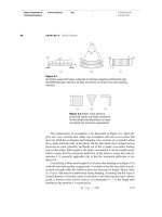
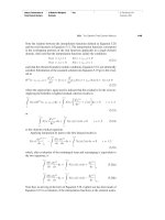
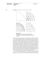
... are first conducted to verify the finite element analysis of melting and solidification Results of finite element analysis are compared with exact solutions of solidification and melting problems given ... for the elements involved in phase change are computed by the method of element removal and reactivation and the use of a new initial temperature at T s to calculate the stress/strain of the solidified ... 2.3 The Method of Element Removal and Reactivation In order to model the phenomena of melting and solidification, the element removal and reactivation method, ͓15͔, is applied An element will be...
Ngày tải lên: 06/05/2014, 08:55

finite element analysis of structural steelwork beam to column bolted connections 2001
... Column flange bending Table - Full Scale Test Results Finite Element Model MYSTRO and LUSAS FEA software was used for the finite element analysis The FEA models were created using command files ... modelled Figure - FEA Elements Element Types At the beginning of the research a number of trial models were created Models with fewer elements as well as models with only shell elements were tried ... lower rows In spite of this the new Green Book theory with the increased connection capacities still had a reserve of approximately 30% Overall the finite element analysis of extended end plate...
Ngày tải lên: 04/06/2014, 13:20

Báo cáo nghiên cứu khoa học: "FINITE ELEMENT ANALYSIS OF ELASTO-PLASTIC BOUNDARY FOR SOME STRUCTURE PROBLEMS" pot
... 10x10=100 Fig Finite element idealisation of axisymmetric Fig Finite element idealisation of axisymmetric problem, mesh AM1 problem, mesh AM2 y p x 100mm 200mm Fig Finite element idealisation of plane ... Prof J F Debongnie, Lectures notes on Finite Element Method University of Liège, 1999 Trang 11 Science & Technology Development, Vol 9, No.8- 2006 [5] M A Crisfield, Non-Linear Finite Element Analysis ... middle of the layer, El is Young’s modulus of the layer material, Gl is the shear modulus of the layer material If the stress at the middle surface of a layer reaches the uniaxial yield stress of...
Ngày tải lên: 22/07/2014, 10:21

finite element analysis of fracture in concrete structures state of the art
... structures, it is appropriate to review the details of the finite element analysis of LEFM Then, in Section 2.3, the finite element analysis of nonlinear discrete fracture mechanics will be presented ... incorporate the model into the finite element analysis is by employing interface elements The first interface element was formulated by FINITE ELEMENT ANALYSIS OF FRACTURE IN CONCRETE STRUCTURES ... difficult and controversial aspects of finite element analysis of reinforced concrete structures Much of the controversy lies in the fact that many finite element models of reinforced concrete have provided...
Ngày tải lên: 24/10/2014, 21:58

An integrated finite element analysis of CFRP laminates from low velocity impact to CAI strength prediction
... (composed of uniform elements-the mesh is too dense to see the individual elements clearly), (b) Mesh (composed of smaller elements around the point of impact and larger elements towards the edge of ... Cohesive elements stiffnesses N Normal strength of cohesive elements S Shear strength of cohesive elements , , T , Shear strength Effective traction of cohesive elements Original thickness of cohesive ... 66 3.1.3 Control of finite element instabilities 68 3.2 Development of FE model 70 iii 3.3 Conclusions 83 Chapter 4FINITE ELEMENT SIMULATIONS OF LOW-VELOCITY IMPACT...
Ngày tải lên: 10/09/2015, 09:04

Three dimensional finite element analysis of earth pressure balance tunnelling
... 107 4.6 SUMMARY OF FIELD RESULTS 109 FINITE ELEMENT STUDY OF C704 EPB TUNNELLING 135 5.1 INTRODUCTION .135 5.2 PROBLEM DEFINITION AND FINITE ELEMENT MESH OF AN EPB EXCAVATION ... three-dimensional finite element analysis, namely (i) the feasibility of conducting three-dimensional analysis without resorting to inordinate amounts of computer resources and time, and (ii) the usefulness of ... EQMR element- by -element quasi-minimal residual Z excav Lshield xv FE finite element FEA Finite element analysis FEM finite element model HCC hyperbolic small strain modified Cam Clay model HMCEA...
Ngày tải lên: 17/09/2015, 17:19

non linear finite element analysis of solids and structures
... Non-linear Finite Element Analysis of Solids and Structures ~ VOLUME 1: ESSENTIALS ~ ~~ ~~ Non-linear Finite Element Analysis of Solids and Structures VOLUME 1: ESSENTIALS M A Crisfield FEA Professor of ... Non-linear Finite Elements, National Agency for Finite Elements (NAFEMS) (1990) Oden, J T., Finite Elements of Nonlinear Continua, McGraw-Hill (1972) Owen, D R J & Hinton, E., Finite Elements in ... length of bar p = geometric factor (equation (1.60)) E = axial strain in bar = final angular inclination of bar 1.5 LIST OF BOOKS ON (OR RELATED TO) NON-LINEAR FINITE ELEMENTS Bathe, K J., Finite Element...
Ngày tải lên: 26/04/2016, 08:47

non linear finite element analysis of solids and structures
... Non-linear Finite Element Analysis of Solids and Structures ~~ ~ Volume 2: Advanced Topics To Kiki, Lou, Max, ArabeIIa Gideon, Gavin, Rosie and Lucy Non-linear Finite Element Analysis of Solids ... non-linear finite element computer program using truss elements’ in conjunction with Dr Shi This chapter describes a finite element computer program that can be considered as the extension of the ... rate of Kirchhoff stress 12.4.1 Alternative derivation of the tangent stiffness matrix 12.5 The tangent stiffness matrix using the Jaumann rate of Cauchy stress 12.5.1 Alternative derivation of...
Ngày tải lên: 26/04/2016, 08:48

fundamentals of finite element analysis - hutton - (mcgraw-hill)
... Fundamentals of Finite Element Analysis Basic Concepts of the Finite Element Method Text © The McGraw−Hill Companies, 2004 1.2 How Does the Finite Element Method Work? 4.5 4.0 Exact Two elements Four elements ... Fundamentals of Finite Element Analysis Basic Concepts of the Finite Element Method Text 1.4 Brief History of the Finite Element Method compute additional, derived variables, such as reaction forces, element ... “Application of the Finite Element Method to Heat Conduction Analysis. ” Nuclear Engineering Design (1966) 17 Hutton: Fundamentals of Finite Element Analysis 18 Basic Concepts of the Finite Element...
Ngày tải lên: 08/04/2014, 10:37

Hutton book - fundametans of finite element analysis
... Fundamentals of Finite Element Analysis Basic Concepts of the Finite Element Method Text © The McGraw−Hill Companies, 2004 1.2 How Does the Finite Element Method Work? 4.5 4.0 Exact Two elements Four elements ... Fundamentals of Finite Element Analysis Basic Concepts of the Finite Element Method Text 1.4 Brief History of the Finite Element Method compute additional, derived variables, such as reaction forces, element ... “Application of the Finite Element Method to Heat Conduction Analysis. ” Nuclear Engineering Design (1966) 17 Hutton: Fundamentals of Finite Element Analysis 18 Basic Concepts of the Finite Element...
Ngày tải lên: 26/05/2014, 03:41

SAP2000 - Three Dimensional Static and Dynamic Finite Element Analysis and Design of Structures
... Comprehensive Software for the Finite Element Modeling, Static, Dynamic and Non-Linear Analysis and Design of Structures Introduction Powerful and Integrated Structural Analysis and Desi gn Software ... Shell Elements Powerful Shell Elements General quadrilateral or triangular element • SAP2000 • Isotropic, Orthotropic and Anisotropy material Powerful Shell Elements Shell Elements Six degrees of ... fast profile optimization • SAP2000 • Non-linear Pushover Analysis General Dynamic Analysis Analysis Options Eigenvalue analysis with an accelerated subspace iteration algorithm • Ritz analysis...
Ngày tải lên: 11/06/2014, 03:16

Finite Element Analysis: Thermomechanics of Solids doc
... 2003 5:00 PM 36 Finite Element Analysis: Thermomechanics of Solids As proof, α j y j ⊗ βk zk = α j βk y j ⊗ zk = Ay j ⊗ Bz k = (A ⊗ B)(y j ⊗ z k ) (2.59) Now, the eigenvalues of A ⊗ In are × ... Page 16 Wednesday, February 19, 2003 4:55 PM 16 Finite Element Analysis: Thermomechanics of Solids Suppose now that v(t), θ, and φ are functions of time As in cylindrical coordinates, d ∂ v′ = ... 22 Finite Element Analysis: Thermomechanics of Solids Verify that T T (a) QQ = Q Q T −1 (b) Q = Q (c) For any × vector a Qa = a [The relation in (c) is general, and Qa represents a rotation of...
Ngày tải lên: 27/06/2014, 15:20

Fundamentals of Finite Element Analysis phần 1 pdf
... Fundamentals of Finite Element Analysis Basic Concepts of the Finite Element Method Text © The McGraw−Hill Companies, 2004 1.2 How Does the Finite Element Method Work? 4.5 4.0 Exact Two elements Four elements ... Fundamentals of Finite Element Analysis Basic Concepts of the Finite Element Method Text 1.4 Brief History of the Finite Element Method compute additional, derived variables, such as reaction forces, element ... “Application of the Finite Element Method to Heat Conduction Analysis. ” Nuclear Engineering Design (1966) 17 Hutton: Fundamentals of Finite Element Analysis 18 Basic Concepts of the Finite Element...
Ngày tải lên: 08/08/2014, 17:20

Fundamentals of Finite Element Analysis phần 2 pps
... length of each element and the direction cosines of element orientation Table 3.2 Element- Node Connectivity Table for Figure 3.2 Node Element i j 2 3 Hutton: Fundamentals of Finite Element Analysis ... modulus of elasticity of the element material 3.4 DIRECT ASSEMBLY OF GLOBAL STIFFNESS MATRIX Having addressed the procedure of transforming the element characteristics of the one-dimensional bar element ... consideration of Figure 3.1b, where multiple elements are connected at a global node, the geometry of the connection determines the relations Hutton: Fundamentals of Finite Element Analysis Truss...
Ngày tải lên: 08/08/2014, 17:20
Fundamentals of Finite Element Analysis phần 3 pps
... same as those of elementary beam theory with the addition of The element is of length L and has two nodes, one at each end The element is connected to other elements only at the nodes Element loading ... Hutton: Fundamentals of Finite Element Analysis Flexure Elements Text © The McGraw−Hill Companies, 2004 4.4 Flexure Element Stiffness Matrix where V is total volume of the element Substituting ... Fundamentals of Finite Element Analysis Flexure Elements Text © The McGraw−Hill Companies, 2004 4.6 Work Equivalence for Distributed Loads Table 4.2 Element Connectivity Global Displacement Element Element...
Ngày tải lên: 08/08/2014, 17:20
Fundamentals of Finite Element Analysis phần 4 pps
... to the beam element begins with consideration of the equilibrium conditions of a differential section taken along the 149 Hutton: Fundamentals of Finite Element Analysis 150 Method of Weighted ... Fundamentals of Finite Element Analysis Method of Weighted Residuals Text © The McGraw−Hill Companies, 2004 5.4 Application of Galerkin’s Method to Structural Elements Galerkin’s finite element method ... formulation of a finite element approach to any type of problem REFERENCES Stasa, F L Applied Element Analysis for Engineers New York: Holt, Rinehart, and Winston, 1985 Burnett, D S Finite Element Analysis...
Ngày tải lên: 08/08/2014, 17:20
Fundamentals of Finite Element Analysis phần 5 docx
... Burnett, D S Finite Element Analysis Reading, MA: Addison-Wesley, 1987 Zienkiewicz, O C The Finite Element Method, 3rd ed London: McGraw-Hill, 1977 Stasa, F L Applied Finite Element Analysis for ... if the finite element model of the problem is composed of M elements, one boundary condition is imposed at node of element and the second boundary condition is imposed at node of element M The ... quadrilateral element having the parent element whose interpolation functions are given by Equation 6.56 Hutton: Fundamentals of Finite Element Analysis Interpolation Functions for General Element...
Ngày tải lên: 08/08/2014, 17:20

Fundamentals of Finite Element Analysis phần 6 pptx
... Example 7.5: (a) Two-dimensional fin (b) Finite element model (c) Element edge convection (d) Element edge convection Hutton: Fundamentals of Finite Element Analysis Applications in Heat Transfer ... (a) ؒ m (b) Figure 7.16 (a) Oil cooler tube of Example 7.9 (b) Element and node numbers for a four -element model Hutton: Fundamentals of Finite Element Analysis Applications in Heat Transfer Text ... What of the element surface areas that are part of the surface area of the volume being modeled? Generally, these outside areas are subjected to convection 269 Hutton: Fundamentals of Finite Element...
Ngày tải lên: 08/08/2014, 17:20

Fundamentals of Finite Element Analysis phần 7 pdf
... Fluid Mechanics 15 16 14 Hutton: Fundamentals of Finite Element Analysis © The McGraw−Hill Companies, 2004 309 Hutton: Fundamentals of Finite Element Analysis 310 Applications in Fluid Mechanics ... 14 13 12 29 11 10 Figure 8.8 Lines of constant velocity potential for the finite element solution of Example 8.2 311 Hutton: Fundamentals of Finite Element Analysis 312 Applications in Fluid ... McGrawHill, 1983 Stasa, F L Applied Finite Element Analysis for Engineers New York: Holt, Rinehart and Winston, 1985 323 Hutton: Fundamentals of Finite Element Analysis 324 Applications in Fluid...
Ngày tải lên: 08/08/2014, 17:20
Fundamentals of Finite Element Analysis phần 8 pptx
... knowledge of engineering principles Automated model definition is a nicety of modern finite element software; automated analysis of results is not Analysis of results is the postprocessing phase of finite ... problems often involve surface forces in the form of internal or external pressure and body forces arising from rotation of the body (centrifugal Hutton: Fundamentals of Finite Element Analysis ... The element strain and stress components, as computed, are expressed in the element coordinate system In general, for the elements commonly used in Hutton: Fundamentals of Finite Element Analysis...
Ngày tải lên: 08/08/2014, 17:20