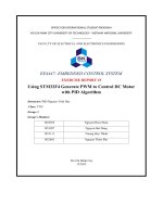
block diagram dc motor speed control system

DC motor speed stabilizer system uses PID algorithm
... function block configuration, programming algorithm flowchart for PLCs, and monitoring console design for a small DC motor drive system model to verify Keywords: PLC,PID, motor speed stabilizer, DC motor, ... and large scale automatic control systems, PLC (Programmable Logic Controller) is used as the control device for the system In production, the transmission system using motors takes a large proportion ... will give a drive model with DC motor and related control parts to reexperiment the theory presented above in Figure Figure The practice model PID speed control for DC motor Detailed descriptions
Ngày tải lên: 24/10/2022, 18:05

Design the high speed control system for the synchronization between the rotary table and linear motion lead screw
... Separate control of main motor circular axis and X, Y, Z axes The system is stable during operation Motor runs precisely at high speed Design control interface for automatic product picking system ... result of high -speed synchronous control of Y-axis: Stroke graph: Speed graph: Figure 4.50: The line chart illustrate the high -speed synchronous control of Y-Axis Figure 4.51: Actual speed of Y-axis ... set parameters to control axes according to needs In the frame “MAGNET CONTROL? ?? are the buttons to control the magnet As soon as the system is started, to control the servo motor it is necessary
Ngày tải lên: 28/12/2023, 18:51

project subject encoder motor speed control by pid
... Bit1=In Bit0=In DDRC=(0<<DDC7) | (0<<DDC6) | (0<<DDC5) | (0<<DDC4) | (0<<DDC3) | (0<<DDC2) | (0<<DDC1) | (0<<DDC0); // State: Bit7=T Bit6=T Bit5=T ... set speed and actual speed) , integral of error, and derivative of error PWM Output Function (pwm _speed_ out): PWM Mapping: Maps the PID control output to PWM signals for controlling the motor speed ... motor speed The PID controller continuously adjusts the motor input to minimize the difference between the setpoint and the actual speed Trang 1010 Software Programing We implement a speed control
Ngày tải lên: 17/06/2024, 17:07

control speed of DC motor using thysistor and transitor
... for low- power DC motor, … + Disadvantage: no using for high-power DC motor, only control small devices, slow speed, … CHAPTER III: DESIGN SPEED CONTROL OF DC MOTOR CIRCUIT 3.1: Control circuit ... speed control of DC motor This paper studies different speed control techniques of DC motor and Supervisor: Nguyen Van Lanh Page makes a comparative study of different converter based speed controller ... have two ways control speed of DC motor: - Control using thysistors + Advantage: using for high-power DC motor, fast speed, applying for devices, … + Disadvantage: complex structure, - Control using
Ngày tải lên: 27/02/2019, 11:40

Fractional order adaptive kalman filter for sensorless speed control of dc motor
... Simulation and experimental results The block diagram of the sensorless speed control strategy is shown in Figure In the block diagram, a PI controller, motor driver, DC motor and a FOAKF state estimator ... various control approaches are used, in general emphasis is given to controlling the speed of the machines To achieve effective speed control, a closed-loop control system is used, in which motor ... the use of electric motors, hydraulics and pneumatic systems To drive these systems, motors are required For motion transmission systems generally, AC motors are used while DC motors are used in
Ngày tải lên: 01/03/2024, 15:59

AN0843 speed control of 3 phase induction motor using PIC18 microcontrollers
... 10-bit ADC channel on the PICmicro microcontroller determines the motor speed The microcontroller uses the ADC results to calculate the duty cycle of the PWMs and thus, the motor frequency The ADC ... frequencies Slip Speed Base Speed Synchronous speed minus base speed Speed specified on the nameplate of an induction motor Stator Break Down Torque Synchronous Motor Maximum torque on the speed- torque ... speed The speed listed on the motor nameplate is the base speed Some manufacturers also provide the slip as a percentage of synchronous speed as shown in Equation Base Speed N = Synchronous Speed
Ngày tải lên: 11/01/2016, 14:28

AN0893 low cost bidirectional brushed DC motor control using the PIC16F684
... Capture, Compare, PWM (ECCP) on the PIC16F684 for bidirectional, brushed DC (BDC) motor control Low-cost brushed DC motor control can be used in applications such as intelligent toys, small appliances ... bidirectional BDC motor control This application note will discuss the following: • • • • • Calculating ECCP PWM Parameters Initializing the ECCP in full-bridge PWM mode Bidirectional BDC Motor Control ... can be performed with a BDC motor by measuring the back EMF voltage from the motor (see Figure 3) The BDC RPM is directly proportional to the back EMF voltage Since a BDC motor can be modeled as
Ngày tải lên: 11/01/2016, 14:35

AN0899 brushless DC motor control using PIC18FXX31 MCUs
... PWMs A B C DC+ Off DC- DC+ DC- Off PWM5(Q5) PWM2(Q2) Off DC- DC+ PWM5(Q5) PWM0(Q0) DC- Off DC+ PWM3(Q3) PWM0(Q0) DC- DC+ Off PWM3(Q3) PWM4(Q4) Off DC+ DC- SEQUENCE FOR ROTATING THE MOTOR IN COUNTERCLOCKWISE ... PWM5(Q5) PWM2(Q2) Off DC- DC+ PWM1(Q1) PWM2(Q2) DC+ DC- Off PWM1(Q1) PWM4(Q4) DC+ Off DC- PWM3(Q3) PWM4(Q4) Off DC+ DC- 0 PWM3(Q3) PWM0(Q0) DC- DC+ Off PWM5(Q5) PWM0(Q0) DC- Off DC+ DS00899A-page ... The following section explains how PCPWM, IC and ADCs are used for open-loop control FIGURE 1: BLDC MOTOR CONTROL BLOCK DIAGRAM REF DC+ AN1 IMOTOR Hall A Hall B Hall C Temp PWM5 AN0 Run/Stop
Ngày tải lên: 11/01/2016, 14:35

AN1175 sensorless brushless DC motor control with PIC16
... brushless motors, and the differences are: MOTOR CONTROL BLDC motor control consists of two parts Part is commutating the motor at the most efficient rate Part is regulating the speed of the motor ... - Microcontroller - Microcontroller Power Supply - Speed Set-point Input Motor Power Driver All BLDC motors require three half-bridge driver stages Each stage controls one phase of the motor, ... BLDC motor over a brushed DC motor, we can enumerate the following: • The absence of the mechanical commutator allows higher speeds • Brush performance limits the transient response in the DC motor
Ngày tải lên: 11/01/2016, 16:47

Rotor speed control for the PMSG Wind turbine system using dynamic surface control algorithm
... speed for maximum power extraction Sliding Mode Control and Backstepping Sliding Mode Controller are considered as the popular techniques in nonlinear system design since the derived system control ... CONTROLLER DESIGN In this section, from the system? ??s model in section 2, a control is proposed base on DSC controller and the stability of closed-loop system is analyzed 3.1 Dynamic Surface controller ... rotation speed for varying wind speeds However, these control strategies may not provide satisfactory performances due to the system nonlinearity of the PMSG To improve the quality of the controller,
Ngày tải lên: 27/09/2020, 14:41

novel observer scheme of fuzzy mras sensorless speed control of induction motor drive
... design of sensorless control schemes of the of induction motor drive to improve the stability and the robustness of the control system The advantages of speed sensorless induction motor derives are ... speed is possible only when the rotor flux is time-variant The overall block diagram of direct field orientation control for induction motor is given in Figure If the model of the induction motor ... optimization control of an indirect vector controlled induction motor drive, IEEE-IECOM [13] Won, C., Kim, S and Bose, B.K (1992) ‘Robust position control of induction motor using fuzzy logic control? ??,
Ngày tải lên: 04/12/2022, 16:01

Modeling, investigating and design control system of the direct curent motor
... current motor is a peripheral device that is widely used because of its simple control and affordable price A direct current motor DC (DC is stand for “Direct Current Motors”) is a mortor controlled ... ground wire – GND) DC motor is a direct curent motor with continuous rotation function DC motors come in many types, each with different specific functions Around us, small DC motors are used in ... industry, applications of DC motors include conveyors and turntables, … using large power DC motors in applications such as brakes and reversing… We have some examples such as DC motor in fan, hydraulic
Ngày tải lên: 21/03/2024, 17:25
Using stm32f4 generate pwm to control dc motor with pid algorithm
... L298N DriverThe L298N is a dual H-Bridge motor driver which allows speed and direction control of two DC motors at the same time The module can drive DC motors that have voltages between 5 and ... Encoder DC Servo JGB37-520 333RPMJGB37-520 DC Geared Motor DC Servo Motor is integrated with a two-channel A, B Encoder to help read and accurately adjust the position and rotation of the motor ... accuracy: PID control, Automatic robot action, JGB37-520 DC Geared Motor DC Servo Motor has a metal structure for durability and high stability, used in robot models, vehicles, boats, , the motor' s
Ngày tải lên: 08/04/2024, 17:40

MATLAB control system toolbox & SIMULINK
... http://www.mathworks.com 1 Control System Toolbox Control System Toolbox là mt th vi$n ca Matlab dùng trong l"nh vc iu khi&n t ng. Cùng vi các l$nh ca Matlab, tp l$nh ca Control System Toolbox ... Control System Toolbox & Simulink 1 Control System Toolbox & SIMULINK ng dng phân ... dng tìm c hàm cn quan tâm. Có th& k& ra mt s th vi$n trong Matlab nh sau : - Control System (dành cho iu khi&n t ng) - Finacial Toolbox (l"nh vc kinh t) - Fuzzy
Ngày tải lên: 03/11/2013, 20:02
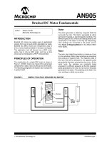
Tài liệu Brushed DC Motor Fundamentals doc
... A drawback to SWDC motors is that they do not have precise speed control like PMDC and SHWDC motors have. FIGURE 4: SERIES-WOUND DC MOTORS Armature Brush Permanent Magnet Poles DC Voltage Supply ... and series-wound motors. As shown in Figure 5, CWDC motors employ both a series and a shunt field. The performance of a CWDC motor is a combination of SWDC and SHWDC motors. CWDC motors have higher ... torque than a SHWDC motor while offering better speed control than SWDC motor. FIGURE 5: COMPOUND-WOUND DC MOTORS BASIC DRIVE CIRCUITS Drive circuits are used in applications where a control- ler
Ngày tải lên: 22/12/2013, 14:15

PLC communications in a process control system
... PROCESS CONTROL SYSTEM by GR MacKenzie, AEG Communication has become a major part of any process control automation system. Today PLC commu nication is as much for data acquisition as plant control. ... itself to prevent a failure of the interface from affecting the bus. Contact IDC http://www.idc-online.com © Electricity + Control 1(a) Point-to-point topology 1(b) mesh topology. Figure 2(a) Tree ... communication there immediately arose the problem of control of the bus. In point to point communication the control is a master-slave type control. This works well,as if either user fails, no
Ngày tải lên: 25/12/2013, 08:50

Tài liệu Mechatronics DC Motor / Tachometer Closed-Loop Speed Control System ppt
... 0.5 A V @ 1.0 A A schematic diagram of a DC motor is shown in Figure Figure Schematic Diagram of a DC Motor Mechatronics DC Motor / Tachometer Closed-Loop Speed Control System Kevin Craig 10 Motion ... assumptions made for the DC motor model, as the analog tachometer is a DC generator - a DC motor in reverse Mechatronics DC Motor / Tachometer Closed-Loop Speed Control System Kevin Craig 16 Mathematical ... The motor used in this system is the Honeywell 22VM51-020-5 DC Motor with Tachometer The factory specifications are shown in Table Mechatronics DC Motor / Tachometer Closed-Loop Speed Control System...
Ngày tải lên: 25/01/2014, 13:20
Numerical analysis of a brushless permanent magnet DC motor using coupled systems
... permanent magnet motors are broadly classified into: • Brushed DC motor (or) PMDC commutator motor: The construction of a permanent magnet DC motor( PMDC) is similar to a DC conventional motor with the ... determination of torque -speed characteristics of the BLDC motor BLDC motors cannot work without the electronic controllers In order to analyze the motor with a controller as an actual system, a new approach ... rotor BLDC motor configuration 1.4 Exterior rotor BLDC motor configuration 1.5 Axial field type BLDC motor configuration 1.6 Basic components of the BLDC motor...
Ngày tải lên: 16/09/2015, 12:26

DC motor position and speed tracking (PAST) system using neural networks
... Evaluation of the AIM 42 Figure 3.7: Block Diagram for Speed Tracking 42 Figure 3.8: Speed Tracking System for the DC Motor 45 DC motor Position and Speed Tracking(PAST) System Using Neural Networks ... PAST system 3.2 Model of the DC Motor DC motors have been used in advanced control algorithms in DC drives because of their stable and straightforward characteristics The DC motor takes in a DC Motor ... Actual (DC Motor) Speeds with the Closed Loop Control System Figure 4.40: 90 91 Speed Error Between the Reference (desired) and the Actual (DC Motor) Positions with the Closed Loop Control System...
Ngày tải lên: 04/10/2015, 10:25

SIMULATION AND SPEED CONTROL OF INDUCTION MOTOR DRIVES
... following block diagram shows the closed loop V/f control using a VSI 38 | P a g e Simulation and Speed Control of Induction Motor Drives 2012 Figure 4.4: Block diagram for closed loop V/f control ... suitable speed control methods The basic block diagram of an electrical drive is shown below: SOURCE POWER MODULATOR MOTOR CONTROL UNIT LOAD SENSING UNIT INPUT COMMAND Figure 1.1: Block diagram ... drive Earlier only dc motors were employed for drives requiring variable speeds due to ease of their speed control methods The conventional methods of speed control of an induction motor were either...
Ngày tải lên: 18/12/2013, 22:06
Bạn có muốn tìm thêm với từ khóa: