air gas handling systems steam plants are classif

ARNOLD, K. (1999). Design of Gas-Handling Systems and Facilities (2nd ed.) Episode 1 Part 1 pps
... Ph.D., RE Metairie, Louisiana xiv CHAPTER Overview of Gas- Handling Facilities * The objective of a gas- handling facility is to separate natural gas, condensate, or oil and water from a gas- producing ... acid gas treating, and gas processing As was the case with Volume 1, this text covers topics that are common to both oil- and gashandling production facilities, such as pressure relief systems; ... natural gas for sales Gas sweetening, the removal of corrosive sulfur compounds from natural gas, is discussed in Chapter 7; methods of gas dehydration are the subject of Chapter 8, and gas processing...
Ngày tải lên: 06/08/2014, 02:20

ARNOLD, K. (1999). Design of Gas-Handling Systems and Facilities (2nd ed.) Episode 1 Part 2 doc
... Water condensers with arnine Reboilers with steam Reboilers with hot oil 00-psi gas with 500-psi gas 1,000-psi gas with 1,000-psi gas ,000-psi gas chiller (gas- C3) MEA exchanger U 35-40 40-50 60-70 ... Design of GAS- HANDLING Systems and Facilities Table 2-8 Typical Bare-Tube Overall Heat-Transfer Coefficients, U for Shell and Tube Heat Exchangers Btu/hr-ft2-°F Service Water with 100-psi gas Water ... on page 20) 18 Design of GAS- HANDLING Systems and Facilities Table 2-2 Pipe Coil Data Norn, Size in 21A Sch No OD in !D in Internal Surface Area (f^/ft) External Surface Area (fP/ft) S40 X80 160...
Ngày tải lên: 06/08/2014, 02:20

ARNOLD, K. (1999). Design of Gas-Handling Systems and Facilities (2nd ed.) Episode 1 Part 3 pps
... GAS- HANDLING Systems and Facilities Natural Gas Sensible Heat Duty at Constant Pressure The sensible heat duty for natural gas at constant pressure is: where Qg = gas flow rate, MMscfd Cg = gas ... where: where Pr = gas reduced pressure P = gas pressure, psia Pc = gas pseudo critical pressure, psia Tj = gas reduced temperature Ta = gas average temperature, °R = 1/2 (Tj + T2) Tc = gas pseudo critical ... tubes The common pitches for square patterns are %-in OD on 52 Design of GAS- HANDLING Systems and Facilities I -in and 1-in OD on l!4-in For triangular patterns these are %-in OD on %-in., M-in OD...
Ngày tải lên: 06/08/2014, 02:20

ARNOLD, K. (1999). Design of Gas-Handling Systems and Facilities (2nd ed.) Episode 1 Part 4 pdf
... outside surface area of the bare tube (neglecting fins) is used in the heat 76 Design of GAS- HANDLING Systems and Facilities Figure 3-15 Side elevations of air coolers (From Gas Processors Suppliers ... 75 — 3.5 90 _ 4.2 Air and Flue -Gas Coolers Use one-half of value given for hydrocarbon \gas coolers Steam Condensers (Atmospheric pressure & above) Pure steam (rf = 0.005) Steam with non-condensable ... temperature, °F tj = ambient air temperature, °F Table 3-7 gives the external area of fin tubes per square foot of bundle surface area From this data the area of bundle surface area can be calculated...
Ngày tải lên: 06/08/2014, 02:20

ARNOLD, K. (1999). Design of Gas-Handling Systems and Facilities (2nd ed.) Episode 1 Part 5 pps
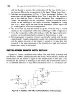
... the gas through the shell Calculate LMTD: Correction factor (Figure 3-10): Calculate number of tubes: 90 Design of GAS- HANDLING Systems and Facilities From Table 3-4 for 1-in OD, IM-in, square ... (From Gas Processors Suppliers Association, Engineering Data Book.} 95 96 Design of GAS- HANDLING Systems and Facilities Figure 4-2, Vapor-solid equilibrium constant for propane, (from Gas Processors ... Services, Inc 109 110 Design of GAS- HANDLING Systems and Facilities LTX UNITS These units are designed to allow hydrates to form and to melt them with the heat of the incoming gas stream before they can...
Ngày tải lên: 06/08/2014, 02:20

ARNOLD, K. (1999). Design of Gas-Handling Systems and Facilities (2nd ed.) Episode 1 Part 6 potx
... (52.3°API) d Water duty: Gas is saturated with water at 8,000 psig and 224°F From Figure 4-6, we have: 126 Design of GAS- HANDLING Systems and Facilities lb water/MMscf of wet gas at reservoir conditions ... Unless the gas well produces at low pressure (less than 500 psi) and the gas contains very little condensate (less than 100 bpd), the additional expendi- 132 Design of GAS- HANDLING Systems and ... based on noise or inability to use corrosion inhibitors In gas lines it is recommended that the maximum 118 Design of GAS- HANDLING' Systems and Facilities allowable velocity would be 60 ft/sec,...
Ngày tải lên: 06/08/2014, 02:20
ARNOLD, K. (1999). Design of Gas-Handling Systems and Facilities (2nd ed.) Episode 1 Part 7 ppsx
... acid, thus the term "acid gas. " Natural gas with H2S or other sulfur compounds present is called "sour gas, " while gas with only CO2 is called "sweet." Both H2S and CO2 are undesirable, as they ... Engineering Services, Inc 151 152 Design of GAS- HANDLING Systems and Facilities Table 7-1 Physiological Effects of H2S Concentrations in Air Concentrations in Air Percent by Volume 0.00013 Parts per ... sizing parameters for iron sponge and amine systems are presented, as these are the most common field gas treating processes currently employed and they are not proprietary in nature (text continued...
Ngày tải lên: 06/08/2014, 02:20
ARNOLD, K. (1999). Design of Gas-Handling Systems and Facilities (2nd ed.) Episode 1 Part 8 doc
... near atmos- 170 Design of GAS- HANDLING Systems and Facilities pherie This causes the acid -gas partial pressures to decrease; the acid gases evolve to the vapor phase and are removed The regenerated ... steel 182 Design of GAS- HANDLING Systems and Facilities Figure 7-13 CO2 removal, no h^S The superficial gas velocity (that is, gas flow rate divided by vessel cross-sectional area) through the ... required Diisopropanolamine Systems Diisopropanolamine (DIPA) is a secondary amine used in the Shell ADIP® process to sweeten natural gas DIPA systems are similar to MEA systems but offer the following...
Ngày tải lên: 06/08/2014, 02:20
ARNOLD, K. (1999). Design of Gas-Handling Systems and Facilities (2nd ed.) Episode 1 Part 9 pdf
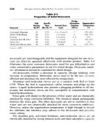
... a Ib/MMscf specification, to trays are common 200 Design of GAS- HANDLING Systems and Facilities Figure 8-4 Typical glycol contactor in which gas and liquid are in counter-current flow As with ... condensers are typically air- cooled, fin-fan exchangers Their duty can be determined from the concepts in Chapter as required to cool the overhead gases and condense the overhead steam Acid Gas Treating ... dehydration systems that are the most common methods of dehydration used *Reviewed for the 1999 edition by Lindsey S Stinson of Paragon Engineering Services, Inc 195 196 Design of GAS- HANDLING Systems...
Ngày tải lên: 06/08/2014, 02:20

ARNOLD, K. (1999). Design of Gas-Handling Systems and Facilities (2nd ed.) Episode 1 Part 10 pdf
... service to dehydrate gas The cooling gas could either be wet gas or gas that has already been dehydrated If wet gas is used, it must be dehydrated after being used as cooling gas A, hot tower will ... Design of GAS- HANDLING Systems and Facilities mit some of the wet gas to bypass the desiccant bed Only a small amount of wet, bypassed gas is needed to cause freezeups in cryogenic plants Ledges ... Design of GAS- HANDLING Systems and Facilities Rich glycol heat duty Lean glycol flow rate (W]ean) Calculation of T4 Gas Dehydration * Glycol/glycol preheater—calculate lean side Temperature * Gas/ glycol...
Ngày tải lên: 06/08/2014, 02:20
ARNOLD, K. (1999). Design of Gas-Handling Systems and Facilities (2nd ed.) Episode 2 Part 1 docx
... for rich gas streams where it is not desired to recover ethane Lean oil plants are expensive and hard to operate They are rarely designed as new plants anymore Existing lean oil plants are sometimes ... light ends are eliminated from the rich oil and a separation stage where the natural gas liquids are separated from the rich oil These plants are not as popular as they once were and are rarely, ... Assuming the cooling gas is at 110°F, the volume of gas required for cooling will be * Steam tables ** Specific heat of gas at the average temperature CHAPTER Gas Processing* The term "gas processing"...
Ngày tải lên: 06/08/2014, 02:20

ARNOLD, K. (1999). Design of Gas-Handling Systems and Facilities (2nd ed.) Episode 2 Part 2 pps
... reciprocating flow 280 Design of GAS- HANDLING Systems and Facilities Discharge Coolers These cool the interstage gas They may also be required to cool the discharge gas prior to gas treating or dehydration ... Design of GAS- HANDLING Systems and Facilities Figure TO-9 Centrifugal compressor {Courtesy of Dresser-Rand Company,! head to the gas This is then converted to pressure head as the gas is slowed ... the cylinder or until a flare valve or relief valve is actuated Suction throttle valves are common in gas- lift service to minimize the action of the flare valve Flow from gas- lift wells decreases...
Ngày tải lên: 06/08/2014, 02:20
ARNOLD, K. (1999). Design of Gas-Handling Systems and Facilities (2nd ed.) Episode 2 Part 3 potx
... effective flow areas have less pressure drop and better efficiencies, The effects of the seat area, the lift area, and the flow paths are automati- 302 Design of GAS- HANDLING Systems and Facilities ... cylinders are typical of low horsepower air compressors Single-acting process compressors are typically double-act- Figure 11-4 Single acting cylinders (Courtesy of Dresser-Rand.) 290 Design of GAS- HANDLING ... applications Frames are typically classified as separable (balanced-opposed) or integral-type, as shown in Figure 11-3 Separable (balanced-opposed) frames are characterized by an adjacent pair of crank...
Ngày tải lên: 06/08/2014, 02:20
ARNOLD, K. (1999). Design of Gas-Handling Systems and Facilities (2nd ed.) Episode 2 Part 4 pdf
... lubrication systems are 314 Design of GAS- HANDLING Systems and Facilities the least expensive and are used in small air compressors Forced-feed systems are used for almost all oilfield gas compression ... the AT of the gas is less than 150°F and discharge gas temperature is less than 210°F Forced coolant systems using a mixture of glycol and water are the most common for natural gas compressors ... of GAS- HANDLING Systems and Facilities In addition to the unbalanced forces and moments, the foundation must absorb the moments produced by the gas torque This is the torque created by the gas...
Ngày tải lên: 06/08/2014, 02:20

ARNOLD, K. (1999). Design of Gas-Handling Systems and Facilities (2nd ed.) Episode 2 Part 5 pps
... Protection Pressure vessels handling salt water and fluids containing signficiant amounts of H2S and CO2 require corrosion protection Common corro- 350 Design of GAS- HANDLING Systems and Facilities ... Relief valves are an essential element in the facility safety system *Reviewed for the 1999 edition by Mary E Thro of Paragon Engineering Services, Inc 355 356 Design of GAS- HANDLING Systems and ... Pressure Relief 357 are a result of relief valves not being adequately sized to handle the gas blowby condition Note: Liquid dump valves are normally fail closed to prevent gas blowby That means...
Ngày tải lên: 06/08/2014, 02:20

ARNOLD, K. (1999). Design of Gas-Handling Systems and Facilities (2nd ed.) Episode 2 Part 6 docx
... Flow Rate for Gas The flow rate for gas through a given orifice area or the area required for a given flow rate is obtained by: where QM = maximum flow, scfm a = actual orifice area, in.2 Kd ... There are no precise formulas for calculating orifice area for twophase flow The common convention is to calculate the area required for the gas flow as if there were no liquid present and the area ... the liquid flow as if there were no gas present The two areas are then added to approximate the area required for two-phase flow Standard Sizes Relief valves are most often sold using the standard...
Ngày tải lên: 06/08/2014, 02:20
ARNOLD, K. (1999). Design of Gas-Handling Systems and Facilities (2nd ed.) Episode 2 Part 7 docx
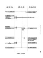
... ANNUNCIATION SYSTEMS These systems give early warning of impending trouble to allow personnel to take corrective action prior to a shut-in, and provide informa- 406 Design of GAS- HANDLING Systems ... Although these symbols are used extensively in U.S production facilities, they are not used in other industries They are widely used overseas and are understood by all who are involved in production ... All the conditions tend to be more likely to lead to 394 Design of GAS- HANDLING Systems and Facilities injury the longer people are exposed to the situation Therefore, escape routes, lighting,...
Ngày tải lên: 06/08/2014, 02:20
ARNOLD, K. (1999). Design of Gas-Handling Systems and Facilities (2nd ed.) Episode 2 Part 8 docx
... occurred where gas has migrated through the drain system to an unclassified area where welding, or other hot work, was being performed See Chapter 15 420 Design of GAS- HANDLING Systems and Facilities ... Electrical Area Classification Another common mistake often uncovered is electrical equipment which is not consistent with the design area classification See Chapter 17 SAFETY MANAGEMENT SYSTEMS ... Valves, and Fittings Table A B C D E F G H I J K L M N P (Spare) Q (Spare) R (Spare) SV AA BB CC (Not Prepared) DD EE FF GG Pressure Kanng Classification Service Non-corrosive Hydrocarbons and Glycol...
Ngày tải lên: 06/08/2014, 02:20

ARNOLD, K. (1999). Design of Gas-Handling Systems and Facilities (2nd ed.) Episode 2 Part 9 ppt
... of gas and requires the area to be classified Figure 15-22 Insulation is necessary because the compressor is a potential source of gas and requires the area to be cbssified 460 Design of GAS- HANDLING ... isolation barriers for surfaces hotter than 400°F that are located within electrically classified areas Surfaces in electrically unclassified areas are only insulated or isolated if necessary for personnel ... and is not in a classified area 458 Design of GAS- HANDLING Systems and Facilities Figure 15*19 Insulation on this fire water pump is not necessary because it is not a hydrocarbon handling vessel...
Ngày tải lên: 06/08/2014, 02:20
ARNOLD, K. (1999). Design of Gas-Handling Systems and Facilities (2nd ed.) Episode 2 Part 10 pptx
... sour gas and keep them from being dispersed in the atmosphere Figure 15-26 Flange protector types 464 Design of GAS- HANDLING Systems and Facilities Vessel Drains If vessel drain valves are used ... is to direct a stream of hot gases against the blading of a turbine rotor As shown in Figures 16-6 and 16-7, the gas turbine consists of 478 Design of GAS- HANDLING Systems and Facilities Figure ... Fundamentals The basic gas turbine engine is described by the idealized Brayton air cycle as shown in Figure 16-8 In this cycle, air enters the air compressor (also called the "gas producer") at Point...
Ngày tải lên: 06/08/2014, 02:20