2d and 3d design

Tài liệu Introduction to AutoCAD 2009 2D and 3D Design- P1 pdf
... system determines the position in units of any 2D point in the drawing area (2D Drafting & Annotation and Classic AutoCAD) and any point in 3D space (3D Modeling) Drawings are usually constructed ... Command palette Two palettes which may be frequently used are the DesignCenter palette and the Properties palette These can be called to screen from icons in the Standard Annotation toolbar ● ● DesignCenter ... constructed – the 2D Drafting & Annotation, Classic AutoCAD and the 3D Modeling workspace Part of this book deals with 2D drawings, which will be constructed mainly in the 2D Drafting & Annotation...
Ngày tải lên: 24/12/2013, 17:15

Tài liệu Introduction to AutoCAD 2009 2D and 3D Design- P2 pptx
... command line in response to tool prompts By using DYN, drawings – whether in 2D or in 3D format – can be constructed purely from operating and moving the mouse, entering coordinates at the command ... the rubber band of the tool is dragged in the direction in which the line is to be drawn and its distance in units is entered at the command line followed by a right-click ● Line and Polyline ... endpoints and midpoints, to intersections of objects, to centres and quadrants of circles and so on Object Snaps also override snap points even when snap is set on To set Object Snaps – at the command...
Ngày tải lên: 24/12/2013, 17:15

Tài liệu Introduction to AutoCAD 2009 2D and 3D Design- P3 ppt
... left-hand drawing of Fig 5.32 Call Trim The command line shows: Command: _trim Current settings: Projection UCS Edge ϭ None Select cutting edges… Select objects or Ͻselect allϾ: pick the left-hand ... SHX fonts and the Windows True Type fonts Please purchase PDF Split-Merge on www.verypdf.com to remove this watermark The styles shown in Fig 6.21, the ITALIC, ROMAND, ROMANS and STANDARD styles ... from the Modify toolbar, or enter cp or copy at the command line Fig 5.3 First example – Copy Object – outlines The command line shows: Command: _copy Select objects: pick the cross found Select...
Ngày tải lên: 24/12/2013, 17:15
Tài liệu Introduction to AutoCAD 2009 2D and 3D Design- P4 ppt
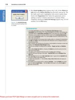
... bottom-right-hand corner of the Hatch and Gradient dialog is clicked (Fig 8.10) the dialog expands to show the Island display style selections (Fig 8.11) Fig 8.10 The More Options arrow of the Hatch and ... 8.11 The Island display style selections in the expanded Hatch and Gradient dialog Construct a drawing which includes three outlines as shown in the left-hand drawing of Fig 8.12 and copy it ... position from the DesignCenter Fig 9.9 Selecting DesignCenter from the Standard Annotation toolbar Fig 9.10 The DesignCenter with the double bed block dragged on screen Notes about DesignCenter palette...
Ngày tải lên: 24/12/2013, 17:15
Tài liệu Introduction to AutoCAD 2009 2D and 3D Design- P5 doc
... 12.8 Example Polysolid and the Polyline forms (Fig 12.8) 2D outlines suitable for 3D models When constructing 2D outlines suitable as a basis for constructing some forms of 3D model, select a tool ... the command line Command: _region Select objects: window the drawing 12 found Select objects: right-click Region created Command: and the Line outline is changed to a region – right-hand drawing ... Home /3D Modeling panel The command line shows: Command: _sphere Specify center point or [3P/2P/Ttr]: 180,170 Specify radius or [Diameter]: 50 Command: Click the Cylinder tool icon in the Home/3D...
Ngày tải lên: 21/01/2014, 23:20

Tài liệu Introduction to AutoCAD 2009 2D and 3D Design- P6 pdf
... be constructed in 3D space using the 3D Array tool 3D models can be mirrored in 3D space using the 3D Mirror tool 3D models can be rotated in 3D space using the 3D Rotate tool 3D models can be ... (left-hand drawing) Click on 3D Mirror in the 3D Operation sub-menu of the Modify drop-down menu The command line shows: Fig 14.16 First example – 3D Mirror – outline of object to be mirrored Command: ... in Fig 14.14 Click 3D Array from the Modify /3D Operations drop-down menu The command line shows: Fig 14.14 Third example – a Polar Array – the 3D model to be arrayed Command: _3darray Select objects:...
Ngày tải lên: 21/01/2014, 23:20
Tài liệu Introduction to AutoCAD 2009 2D and 3D Design- P7 pptx
... example – Rendering Fig 15.40 Third example – Rendering The 3dorbit tool At the command line enter 3dorbit The command line shows: Command: 3dorbit Press ESC or ENTER to exit, or right-click to display ... Preview Saving and opening 3D model drawings 3D model drawings are saved and/ or opened in the same way as are 2D drawings To save a drawing click Save As… in the File drop-down menu and save the ... Fig 17.20 First example – 2D outlines in 3D space The outline in the Isometric view Fig 17.21 First example – 2D outlines in 3D space Second example – 2D outlines in 3D space (Fig 17.25) Place...
Ngày tải lên: 21/01/2014, 23:20

Tài liệu Introduction to AutoCAD 2009 2D and 3D Design- P8 docx
... Add lights and a material to the 3D model and its copied face and render (Fig 18.12) Fig 18.12 Sixth example – Copy faces tool Seventh example – Color faces tool (Fig 18.14) Construct a 3D model ... Editing 3D solid models Introduction to AutoCad 2009 CHAPTER 18 354 Fig 18.18 Second example – 3D models Fig 18.19 Third example – 3D models – details of shapes and sizes Fig 18.20 Third example – 3D ... line The outline and its contents are erased At the command line: Command: enter mv right-click [prompts]: enter right-click [prompts]: right-click Regenerating model Command: and the model appears...
Ngày tải lên: 21/01/2014, 23:20

Tài liệu Introduction to AutoCAD 2009 2D and 3D Design- P9 ppt
... hidden 3D y – Allows walkthroughs in any 3D plane 3Dforbit – controls the viewing of 3D models without constraint 3Dmesh – Creates a 3D mesh in 3D space 3Dmove – Shows a 3D move icon 3Dorbit (3do) ... 14 2D Drafting & Annotation, 4, 89 2D objects in 3D space, 330 2D outlines for 3D, 214 2D tools, 398 2P circles, 33 3D Array tool, 254, 255 3D coordinates, 15 3D DYN, 64 3D Mirror tool, 257 3D ... 252 3D models of buildings, 308 3D model libraries, 250 3D Modeling workspace, 4, 210, 274 3D Navigate, 335 3D Objects tools, 232 3D Rotate tool, 258 3D solid model examples, 352 3D space, 322 3D...
Ngày tải lên: 21/01/2014, 23:20

Tài liệu Introduction to AutoCAD 2009 2D and 3D Design- P10 docx
... hidden 3D y – Allows walkthroughs in any 3D plane 3Dforbit – controls the viewing of 3D models without constraint 3Dmesh – Creates a 3D mesh in 3D space 3Dmove – Shows a 3D move icon 3Dorbit (3do) ... 14 2D Drafting & Annotation, 4, 89 2D objects in 3D space, 330 2D outlines for 3D, 214 2D tools, 398 2P circles, 33 3D Array tool, 254, 255 3D coordinates, 15 3D DYN, 64 3D Mirror tool, 257 3D ... 252 3D models of buildings, 308 3D model libraries, 250 3D Modeling workspace, 4, 210, 274 3D Navigate, 335 3D Objects tools, 232 3D Rotate tool, 258 3D solid model examples, 352 3D space, 322 3D...
Ngày tải lên: 21/01/2014, 23:20

Introduction to AutoCAD 2011 2D and 3D Design pot
... constructed – the 2D Drafting & Annotation, AutoCAD Classic, 3D Basics, 3D Modeling Part 1, 2D Design, of this book deals with 2D drawings and these will be constructed mainly in the 2D Drafting & ... coordinate system determines the position in units of any 2D point in the drawing area (2D Drafting & Annotation) and any point in 3D space (3D Modeling) 11 Drawings are usually constructed in templates ... b The prompt Command:_line Specify first point which appears in the command window at the command line (Fig 2.3) Fig 2.3 The prompt appearing at the command line in the Command palette when...
Ngày tải lên: 27/06/2014, 02:20
Introduction to AutoCAD 2008 2D and 3D Design phần 1 potx
... II – 3D Design 13 Introducing 3D modelling Aims of this chapter Introduction The 3D Modeling workspace Methods of calling tools for 3D modelling The Polysolid tool 2D outlines suitable for 3D models ... AutoCAD and 2D Drafting & Annotation) and any point in 3D space (3D Modeling) 14 Drawings are usually constructed in templates with predetermined settings Some templates include borders and title ... the Standard Annotation toolbar, in which the general and Introduction to AutoCAD 2008 Fig 1.10 A left-click on the DesignCenter icon brings the DesignCenter palette to screen Fig 1.11 The DesignCenter...
Ngày tải lên: 09/08/2014, 11:20
Introduction to AutoCAD 2008 2D and 3D Design phần 2 pot
... of objects, to centres and quadrants of circles and so on Osnaps also override snap points even when snap is set on To set Osnaps, at the command line: Command: enter os And the Drafting Settings ... status bar Close the drawing and open a new acadiso.dwt window Left-click on the Line tool icon and enter figures as follows at each prompt of the command line sequence: Command:_line Specify first ... through points or points entered at the command line in response to prompts brought to the command line by using 3P and 2P in answer to the circle command line prompts The Erase tool If an error...
Ngày tải lên: 09/08/2014, 11:20
Introduction to AutoCAD 2008 2D and 3D Design phần 3 ppt
... at the command line When the tool is called, the cursor on screen changes to a hand icon Dragging the hand across screen under mouse movement allows various parts of the Zoom, Pan and templates ... text style and height in the Text sub-dialog Zoom, Pan and templates 73 right of the Text Style field and select Arial from the popup list Enter a height of in the Text height field and in the ... toolbar, or pick Copy from the Modify tools in the 2D Draw control panel (Fig 5.4), or enter cp or copy at the command line The command line shows: Command: _copy Select objects: pick the cross found...
Ngày tải lên: 09/08/2014, 11:20
Introduction to AutoCAD 2008 2D and 3D Design phần 4 pdf
... AutoCAD 2008 – the AutoCAD SHX fonts and the Windows True Type fonts The ITALIC, ROMAND, ROMANS and STANDARD styles shown in Fig 6.33 are AutoCAD text fonts The TIMES and ARIAL styles are Windows True ... Ͻ140Ͼ: right-click Dim: right-click And the 50 and 140 horizontal dimensions are added to the outline Continue to add the right-hand 50 dimension Then when the command line shows: Dim: enter ve (vertical) ... For Dimension Text Edit – te For Quick Leader – l And to exit from the dimension commands – e (Exit) First example – hor and ve (Horizontal and vertical) – Fig 6.10 Construct the outline in Fig...
Ngày tải lên: 09/08/2014, 11:20
Introduction to AutoCAD 2008 2D and 3D Design phần 5 docx
... blocks Fig 9.9 Selecting DesignCenter from the Standard Annotation toolbar Fig 9.10 The DesignCenter with the double bed block dragged on screen Left-click DesignCenter in the Standard Annotation toolbar ... expands to show the Island Display selections (Fig 8.11) Fig 8.10 The More Options arrow of the Hatch and Gradient dialog Construct a drawing which includes three outlines as shown in the lefthand ... diode (LED) symbol and enter w at the command line The Write Block dialog appears (Fig 9.20) Click the button marked with three dots ( ) to the right of the File name and path field and from the Browse...
Ngày tải lên: 09/08/2014, 11:20
Introduction to AutoCAD 2008 2D and 3D Design phần 6 pptx
... Command: Fig 13.6 Example – Polysolid And the Polysolid forms (Fig 13.6) 2D outlines suitable for 3D models When constructing 2D outlines suitable as a basis for constructing some forms of 3D ... current and from the 3D Navigate drop-down menu select Southeast Isometric Call the Polysolid tool with a click on its tool icon in the 3D Make control panel (Fig 13.4) The command line shows: Command:_Polysolid ... outline to be revolved and the solid of revolution Place in the Southeast Isometric View and Zoom to Call the Union tool from the 3D Make control panel The command line shows: Command:_union Select...
Ngày tải lên: 09/08/2014, 11:20

Introduction to AutoCAD 2008 2D and 3D Design phần 7 pdf
... the DesignCenter Arrays of 3D model drawings can be constructed in 3D space using the 3D Array tool 3D models can be mirrored in 3D space using the Mirror 3D tool 3D models can be rotated in 3D ... array and other two solids Place the screen in the 3D Navigate/Right view Construct a cylinder of radius 30 and height 25 and another of radius 25 and height 60 central to the lower part of the 3D ... The modification of 3D models 237 Second example – a Polar Array (Fig 15.13) Use the same star-shaped 3D model Call the 3D Array tool again The command line shows: Command:_3darray Select objects:...
Ngày tải lên: 09/08/2014, 11:20

Introduction to AutoCAD 2008 2D and 3D Design phần 8 ppt
... machine and Fig 16.25 is an exploded and rendered 3D model of the device The 3D Orbit tool At the command line enter 3dorbit The command line shows: Fig 16.23 Second example – Rendering Command: 3dorbit ... example – 2D outlines in 3D space Fig 17.22 First example – 2D outlines in 3D space – The outline in a SW Isometric view Fig 17.23 First example – 2D outlines in 3D space Second example – 2D outlines ... Constructing 2D objects in 3D space In previous chapters of this book we have seen examples of 2D objects constructed with the Polyline, Line, Circle and other 2D tools to form the 3D space 285...
Ngày tải lên: 09/08/2014, 11:20

Introduction to AutoCAD 2008 2D and 3D Design phần 9 ppt
... face Editing 3D solid models 301 Add lights and a material to the 3D model and its copied face and render (Fig 18.15) Seventh example – Color faces tool (Fig 18.18) Construct a 3D model of the ... the pin and its head 3D Navigate/Top view Move the head to the pin and union the two cylinders 3D Navigate/Front view Move the pin into its position in the holder Add lights and materials 3D Navigate/Southwest ... lights and a material to the edited 3D model and render (Fig 18.18) 50 10 R5 Ø220 R90 R70 Ø210 Ø200 Ø40 R35 Fig 18.17 Seventh example – Color faces tool – details of the 3D model Examples of more 3D...
Ngày tải lên: 09/08/2014, 11:20