plc programmable logic controller

plc programmable logic controller
... general PLC issues • To be able to write simple ladder logic programs • Understand the operation of a PLC • PLC History • Ladder Logic and Relays • PLC Programming • PLC Operation • An Example plc ... to make simple logical control decisions. The development of low cost computer has brought the most recent rev- olution, the Programmable Logic Controller (PLC) . The adven...
Ngày tải lên: 01/01/2014, 21:20

Tài liệu PLC MELSEC System Q Programmable Logic Controllers
Ngày tải lên: 15/10/2013, 16:28
Giáo trình Kỹ thuật PLC ( Programable Logic Controller)
... 27 PLC -Programmable Logic Controller 1 TRƯỜNG CAO ĐẲNG CÔNG NGHIỆP VIỆT ĐỨC - TỔ MÔN ĐIỆN TỬ - KỸ THUẬT PLC (Programmable Logic Controller) Tài liệu lưu hành nội bộ PLC -Programmable Logic Controller U1-U2 ... (R) 4 byte ~ Double Word 16 PLC -Programmable Logic Controller Chương 1 -TỔNG QUAN VỀ PLC I. Các kiến thức cơ bản về PLC (Programmable Logic Contro...
Ngày tải lên: 29/10/2013, 19:15

Tài liệu Programmable logic controllers Basic level TP301 – Textbook ppt
... networked PLC systems etc. Consequently, PLC systems by different manufacturers required entirely different programming. Since 1992, an international standard now exists for programmable logic controllers ... B-30 TP301 • Festo Didactic B-1 Chapter 1 The PLC in automation technology 1.1 Introduction The first Programmable Logic Controller (PLC) was developed by a...
Ngày tải lên: 22/12/2013, 18:16

Programmable logic controllers v1 0 1
... Fax (573) 341‐2672 3 | Page Purpose MachMotion’s CNC software, Mach3, is designed to serially communicate with ModBus devices. For extra I/O or tool changers, PLCs can be easily interfaced with our control. In this manual you will learn how to setup the ModBus protocol to communicate with your PLC. Also, you will examine the addressing scheme and the I/O mapping used to easily a...
Ngày tải lên: 28/12/2013, 22:20

Programmable logic controllers 5ed P1
... washing cycle is completed. 1.1.2 The Programmable Logic Controller A programmable logic controller (PLC) is a special form of microprocessor-based controller that uses programmable memory to store instructions ... answer from the answer options. 1. The term PLC stands for: A. Personal logic computer B. Programmable local computer C. Personal logic controller D. Pro...
Ngày tải lên: 10/04/2014, 14:10

Programmable logic controllers 5ed P2
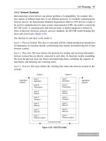
... cable. Communication module Communication port Units located some distance from the PLC Other input/output modules PLC PLC Master PLC Figure 4.19: Use of remote input/output PLC systems. 7 6 5 4 3 2 1 0 Bits Bits 7 6 5 4 3 2 1 0 (a) (b) Figure ... processing is carried out by the master PLC. The cables used for communicating data between remote input/output modules and a central PL...
Ngày tải lên: 10/04/2014, 14:12
Programmable logic controllers 5ed P3
... ring. Often PLCs figure in a hierarchy of communications, with input and output devices at the lowest level, at the next level small PLCs or computers, and at the next level, larger PLCs and computers. ... RSLogix from Rockwell Automation Inc. for Allen-Bradley PLCs, MELSOFTÀGX Developer for Mitsubishi PLCs, and STEP 7ÀMicro/WIN V4 for Siemens PLCs. The software operates on the Windows operat...
Ngày tải lên: 10/04/2014, 14:14
Programmable logic controllers 5ed P4
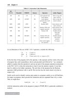
... diagram. S R Input I0,0 SET O0,0 Input I0,1 RESET O0,0 Figure 7.14: SET and RESET (Telemecanique PLC) . S R Input 111/05 Latch 020/00 Input 111/06 Unlatch 020/00 Figure 7.15: Latch and unlatch (Allen-Bradley PLC) . www.newnespress.com 190 Chapter 7 7.6 ... 197 Figures 7.9b and 7.9c show the built-in facilities with Allen-Bradley and Mitsubishi PLCs. With the Mitsubishi PLC (Figure 7.9c),...
Ngày tải lên: 10/04/2014, 14:16
- plc programmable logic controller training plc software
- programmable logic controller plc tutorial siemens simatic s7200 pdf
- programmable logic controller plc applications
- programmable logic controllers plc function block programming
- programmable logic controllers plc state machine programming
- applications of programmable logic controller plc on automation
- programmable logic controllers plc technician program
- programmable logic controllers textbook w plc simulation software