Friction and Lubrication in Mechanical Design Episode 1 Part 10 pptx
Friction and Lubrication in Mechanical Design Episode 1 Part 10 pptx
... Constants SAE 10 1. 18 x 10 -5 2 .18 x 10 -6 1. 58 x 10 -8 1 15 7.5 SAE 20 1. 95 x 10 -’ 3 .15 x 10 -6 1. 36 x 10 -* 12 71. 6 SAE 30 3.35 x 10 -’ 4.60 x 10 -6 1. 41 x 10 -’ 13 60.9 SAE ... loss 1 1 10 -~ 3.4 10 -~ 0.36 3.77 4.88 7600 0 .14 7 5 1 x 10 -7 2.55 x 10 -3 0.325 11 .00 2 .15 8500 0 .17 5 10 1 x 10 -7 1. 5...
Ngày tải lên: 05/08/2014, 09:20
Friction and Lubrication in Mechanical Design Episode 1 Part 5 pptx
... procedure (0 .16 436 x 10 F4 in. and 0 .12 323 x 10 -4rad for Case 1 and 0.30509 x 10 - 4in. and 0.327 21 x 10 -4rad for Case 2) compare favorably with those from the nonlinear f, = 0 .12 e, = ... machining Planing, shaping Sawing Forging Snagging Hot rolling Flame cutting Sand casting 2-8 2 -16 4 -16 4-32 4-63 8 -16 8-32 16 -250 32-63 32 -12 5 32...
Ngày tải lên: 05/08/2014, 09:20

Friction and Lubrication in Mechanical Design Episode 1 Part 1 ppsx
... 62 76 90 97 10 0 10 0 10 0 10 5 11 1 11 3 11 3 11 4 11 5 11 6 11 8 12 1 12 1 12 1 12 3 12 7 13 5 14 2 15 8 16 1 16 1 18 7 209 230 246 24. Traction Drives: Selection and Application, ... 14 17 22 22 22 40 43 46 53 56 56 vii 84. 85. 86. 87. 88. 89. 90. 91. 92. 93. 94. 95. 96. 97. 98. 99. 10 0. 10 1. 10 2. 10 3. 10 4....
Ngày tải lên: 05/08/2014, 09:20

Friction and Lubrication in Mechanical Design Episode 1 Part 2 pdf
... Rolling and Sliding of Bodies,” Wear, 19 68, Vol. 11 , p. 2 91. Kelley, B. W., and Lemaski, A.J., Lubrication of Involute Gearing,” Proc. Inst. Mech. Engrs, 19 67-68, Vol. 18 2, Pt. 3A, p. 17 3. ... Table 2 .1 Values of Factor k 1 1. 5 2 3 5 10 10 0 0.95 0.94 0.92 0.88 0.82 0. 71 0.37 27 Case 4: A Rigid Circular Cylinder Pressed Against a Semi-In...
Ngày tải lên: 05/08/2014, 09:20
Friction and Lubrication in Mechanical Design Episode 1 Part 3 docx
... 10 3 10 2 10 1 0 .1 H,=5 in. - - - - h K 2 10 -2 10 -3 - t, - 10 4 10 -5 10 -6 1 I I I 111 11 I I I 111 111 1 I 11 Ill 11 I I I1 11 111 1 I I I LLU EXAMPLE 4. In ... given in Refs 21- 39. REFERENCES 1. 2. 3. 4. 5. 6. 7. 8. 9. 10 . 11 . 12 . 13 . 14 . 15 . 16 . 17 . Timoshenko, S.P., Theory of Elasticity, McGra...
Ngày tải lên: 05/08/2014, 09:20
Friction and Lubrication in Mechanical Design Episode 1 Part 4 docx
... 2.0 a/b = 0.5 a/b = 8.0 a/b = 0 .12 5 11 2 Fig. 3.8 I12 Fig. 3.9 11 6 Fig. 3 .10 I16 Fig. 3 .11 58 Chapter 3 lp 1 -T Figure 3 .1 The contact of spherical bodies. where ... The rigid body movement (0.6 619 6 x 10 -4 in. ) was also found to compare favorably with Mindlin's prediction (0.67 13 9 x 10 -4 in. ) with a deviation of 1. 41 O/O. E...
Ngày tải lên: 05/08/2014, 09:20
Friction and Lubrication in Mechanical Design Episode 1 Part 6 pdf
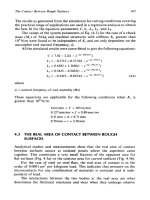
... distribution for rough and smooth surfaces: (a) low load; (b) high load. The Contact Between Rough Surfaces 11 9 8. 9. 10 . 11 . 12 . 13 . 14 . 15 . 16 . 17 . 18 . 19 . 20. 21. 22. 23. 24. ... ASME, Parts I and 11 , 19 91, Vol. 11 3, pp. 13 7 -15 9. Olgac, N., and Zhao, G., “A Relative Stability Study on the Dynamics of the Turning Mechanism,” J. Dyn. M...
Ngày tải lên: 05/08/2014, 09:20
Friction and Lubrication in Mechanical Design Episode 1 Part 7 pdf
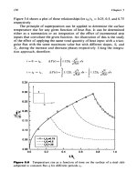
... Considerations in Tribology 14 1 18 00 16 00 14 00 E 5 12 00 E g 10 00 fi 800 G E 600 4 400 200 0 - 0 observation is difficult to perform using the infrared technique [2 11 , because ... as: 1 a= and accordingly: (5 .10 ) (5 .1 1) Blok [2] derived an identical equation for the flash temperature. The contact in Blok's equation is determined an...
Ngày tải lên: 05/08/2014, 09:20

Friction and Lubrication in Mechanical Design Episode 1 Part 8 pdf
... (rolling velocity = 2000 in. /sec, 1= .02 in. , K~=K~~, K~~=K*=.I K~, H,,,=~o~ in. ). Thermal Considerations in Tribology 15 9 4. 5. 6. 7. 8. 9. 10 . 11 . 12 . 13 . 14 . 15 . 16 . 17 . ... 0.6852s + 0.3 214 S2 - Cy, = 0.4 619 + 2.0240($) - 0. 514 5s + 0. 416 8S2 - 2 .16 85S($) + 1. 9 817 S(L/D) Cyy = -7.852 + 10 . 414 - 15 .18 5s + 3.57...
Ngày tải lên: 05/08/2014, 09:20
Friction and Lubrication in Mechanical Design Episode 1 Part 9 ppt
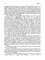
... 19 4 Chapter 6 9x1 o8 8x1 O8 7x1 O8 6x1 0" 5x1 0" 4x10" 3x10⁶ n * B 2x1 o8 1 OS 0 20 40 60 80 10 0 12 0 14 0 16 0 18 0 200 220 240 260 ... 80 10 0 12 0 14 0 16 0 18 0 200 220 240 260 280 AT (OF) Figure 6.20 Bearing chart for P = 500 psi. 9E-6 8E-6 7E-6 6E-6 5E-6 2E-6 1 E-6 0 20 40 60 80 10 0 12 0 14 0 16 0 18...
Ngày tải lên: 05/08/2014, 09:20
- thiết kế bài giảng toán 3 tập 1 part 10 pps
- mechanical design and analysis
- positive and negative spaces in interior design
- data structures and algorithms with objectoriented design patterns in c pdf
- ± pss 25 1 power and energy in circuits mastering physics
- pss 25 1 power and energy in circuits mastering physics