vertical axis wind turbine design calculations

MagLev Wind Turbine Technologies, Inc. (MWTT) & Off Grid Technologies, Inc. (OGT) Vertical Axis Wind Turbine 200 Mega Watt Off Shore Wind Farm (VAWT Off Shore JV) potx
... (http://www.youtube.com/watch?v=xWKNMt9rsIA&feature=player_embedded) The Regenedyne Vertical Axis Wind Turbine (VAWT) is revolutionary in design and is far superior to the conventional systems of today The Regenedyne Vertical Axis Wind Turbine (VAWT) can be ... the unique Vertical Axis design of the proposed wind turbines, aesthetics, noise impacts will not be a factor The low profile, new design will be aesthetically pleasing Because the wind turbines ... 10 Mega Watt Vertical Axis Wind Turbines (VAWT) The project site’s 796 acre area can accommodate a total of up to (100) 10 Mw wind turbines See Appendix for additional proposed wind classification...
Ngày tải lên: 01/04/2014, 00:20

Optimal placement of horizontal - and vertical - axis wind turbines in a wind farm for maximum power generation using a genetic algorithm
... single straight-blade vertical axis wind turbine The geometry of this simple model is shown in Figure 3; the blade is rotating in the counter-clockwise direction while the wind blows from left ... Stream-tube Model for Studying Vertical Axis Wind Turbines AIAA J of Propulsion and Power Vol 4, pp 370-378, 1988 [7] Manwell J.F., Mcgowan J.G and Rogers A.L Wind Energy Explained Wiley, 2009, ... the following expressions for induction factor a and power coefficient Cp for a single vertical axis wind turbine are obtained [7]: ISSN 2076-2895 (Print), ISSN 2076-2909 (Online) ©2012 International...
Ngày tải lên: 05/09/2013, 17:03

A site specific design of a fixed pitch fixed speed wind turbine blade with multiple airfoils as design variable
... optimum alpha -design for only one given wind speed, and consequently function at suboptimum levels for any other wind speed The Phase VI wind turbine will be utilized as a starting point design of ... Some wind turbine airfoils are designed to have a high Cl /Cd and at the same time a high Cl for a given alpha -design angle of attack [12] The optimizations of the Cl /Cd for a given alpha -design ... published experimental data [13] for the Phase VI wind turbine performed in the NASA-Ames wind tunnel located in Moffet Field, California The wind turbine consists of 2-blades with 5.03-meter radius...
Ngày tải lên: 09/09/2015, 10:17
Atmospheric icing on large wind turbine blades
... atmospheric ice along a large wind turbine blade and analyses the ice distribution to identify the most affected areas due to icing Numerical setup The NREL MW wind turbine s blade radius used ... collision efficiency at three different sections of the wind turbine blade Figure Droplet collision efficiency at different sections of NREL MW wind turbine blade 3.2 Atmospheric ice accretion To study ... geometric parameters the ice accretion on the wind turbine blades can be minimized This could reduce the need for de- and anti-icing systems on the wind turbine blades installed in the cold regions...
Ngày tải lên: 05/09/2013, 14:58
Performance analysis of wind turbine systems under different parameters effect
... losses in wind turbine, ρ = air density in kg/m3, A = swept area in m2, Cp =power coefficient of wind turbine, V = wind speed in m/s Mechanical power of wind turbine is directly related to the wind ... MATLAB Modeling of wind turbine The turbine is a wind energy conversion system It consists of an induction generator and other electrical control power requirements The wind turbine is effected ... coefficient [9] λ=ωt×r/V (6) where: r = wind turbine rotor radius, V = wind speed, ωt = mechanical angular rotor speed of the wind turbines Initially, wind speed is not useful until it reach...
Ngày tải lên: 05/09/2013, 16:10
DC bus control of variable speed wind turbine using a buck boost converter
... + - - + ∆α i+1 Fig.7: Wind turbine output power without MPPT control method for low wind speed Fig gives the wind turbine output power without MPPT control method at low wind speed In this case, ... low wind speed The use of the MPPT converter imposes a low DC bus voltage to recover the wind energy at the low winds speeds Fig.8: Wind turbine output power with MPPT control method for low wind ... (∆p/∆d)i+2 >0 N Fig.9 : Wind turbine output power without MPPT control method for high wind speed dopt ‹— di+2 yes ∆P/∆d>0 d ‹— d + ∆d N d ‹— d - ∆d Pi ‹― P i+1 Fig.10 : Wind turbine output power...
Ngày tải lên: 03/01/2014, 19:15
New control strategy for variable speed wind turbine with DC DC converters
... in the MATLAB/Simulink® software environment A Wind turbine model The wind turbine extracts the wind aero dynamical power The model of the wind turbine uses several inputs to estimate precisely ... ‘Dynamic Behavior of a Class of Wind Turbine Generators during Random Wind Fluctuations’, IEEE Transactions on Power Apparatus and Systems, No June 1981 Z Lubosny Wind Turbine Operation in Electric ... Power coefficient curves for 2kW wind turbine model 10 20 30 40 50 Time [s] 60 70 80 90 100 Fig Typical wind profile The aero dynamical power is described by (1) Pwind = ρAν 3C p (λ, θ) Fig Non-inverting...
Ngày tải lên: 03/01/2014, 19:15
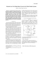
Research on a novel buck boost converter for wind turbine systems
... waveform of the buck-boost inverter under the open loop feedforward compensation control 229 design for wind turbine systems and other distributed generators The two coupled inductors L1 and L2 have ... simulated for different dc source voltages from 50V to 300V, as if it were from a wind turbine source The inverter is designed for a rated power of kW The grid voltage is fixed at 120V/60Hz The switching ... newly proposed inverter are reduced, thereby presenting a more reliable and economical design for wind turbine systems The Fig 12 Output current waveform when the dc voltage is 50V 232 analysis...
Ngày tải lên: 03/01/2014, 19:16

Wind Turbine Health Impact Study: Report of Independent Expert Panel pot
... A: Wind Turbines – Introduction to Wind Energy AA-1 AA.1 Origin of the Wind AA-3 AA.2 Variability of the Wind AA-3 AA.3 Power in the Wind AA-7 AA.4 Wind ... Noise and Vibration by Wind Turbines Wind turbines can produce unwanted sound (referred to as noise) during operation The nature of the sound depends on the design of the wind turbine Propagation ... follows More information on wind turbines may be found in the appendices, particularly in Appendix A 2.1 Wind Turbine Anatomy and Operation Wind turbines utilize the wind, which originates from...
Ngày tải lên: 09/03/2014, 00:20

Catalogue of European Urban Wind Turbine Manufacturers potx
... (wind = m/s) 20) Lifetime 21) Is the machine self-starting Yes 22) Use of an asynchronous generator Yes 23) Yaw control system 24) Upwind or downwind Wind vane 2 10 Wind speed (m/s) Downwind turbine ... (wind = m/s) 20) Lifetime 21) Is the machine self-starting 22) Use of an asynchronous generator 23) Yaw control system 24) Upwind or downwind Yes 18 12 10 No Wind vane Upwind turbine 11 13 Wind ... power Unit Wind speed (m/s) Power (W) 10 50 0,6 kW 2) Rated wind speed 10 m/s 3) Cut-in wind speed m/s None m/s No limit Km/h 37 kg m 10 m 11 4) Cut-out wind speed 5) Maximum wind speed the turbine...
Ngày tải lên: 24/03/2014, 05:20

hugh piggott - windpower workshop building your own wind turbine
... downwind windmill may decide to run upwind This is very difficult to explain, but impressive to watch, when it happens Vertical axis machines We have already looked at one vertical axis wind ... opposite wind turbines' or 'HAWTs' Among theHAWTs, there are the upwind and the downwind varieties, depending on whether the rotor is upwind or downwind of the tower There is another kind known as 'vertical ... compromise Upwind, downwind or vertical axis There are various differenf orientations of rotor you could use (Fig 3.5) Most windmills are what are known as 'horizontal axis Rotor Design 43 Blade...
Ngày tải lên: 04/06/2014, 13:11

Doublyfed induction generator wind turbine modelling for detailed electromagnetic system studies
... 14 Bossany, E.A.: ‘The design of closed loop controllers for wind turbines’, Wind Energy, 2000, 3, (3), pp 149–163 15 Wright, A.D.: ‘Modern control design for flexible wind wurbines’ Report no ... induction generator wind turbines’, IEEE trans Power Syst., 2003, 18, (2), pp 803–809 Hansen, A.D., Sorensen, P., Lov, F., Blaabjerg, F.: ‘Control of variable speed wind turbines with doubly-fed ... des1ign for wind turbines-part 1: Control design, implementation, and initial tests’ Report no TP-500-42437, NREL, 2008 Appendix Parameters that are used in the DFIG WT model rating rated wind speed...
Ngày tải lên: 27/06/2014, 16:06

Practical Design Calculations for Groundwater and Soil Remediation - Chapter 1 pptx
... professionals, their ability to perform or review remediation design calculations varies considerably For some, performing accurate design calculations can become a seemingly insurmountable task Most, ... professionals, their ability to perform or review remediation design calculations varies considerably For some, performing accurate design calculations can become a seemingly insurmountable task The ... Groundwater Remediation This chapter starts with design calculations for capture zone and optimal well spacing The rest of the chapter focuses on design calculations for commonly used in situ or ex...
Ngày tải lên: 10/08/2014, 20:20

Practical Design Calculations for Groundwater and Soil Remediation - Chapter 2 ppt
... zone is important for remediation design This section describes the methodology for such calculations As mentioned, a fence diagram is often drawn to illustrate the vertical and areal extents of ... from aquifer tests Using these collected data, engineering calculations are then performed to assist site remediation Common engineering calculations include: Mass and volume of soil excavated during ... describes all the above-needed engineering calculations, except the last two, which will be covered in Chapter Discussions will also be presented concerning the calculations related to site activities,...
Ngày tải lên: 10/08/2014, 20:20

Practical Design Calculations for Groundwater and Soil Remediation - Chapter 3 potx
... in the aquifer? This chapter illustrates the basic calculations needed to answer most of the above questions The first section presents the calculations for groundwater movement and clarifies some ... chapter three Plume migration in groundwater and soil In Chapter two we illustrated the necessary calculations for site characterization and remedial investigation Generally, from the RI activities ... convert the hydraulic conductivity from gpd/ft2 to m/day The factor was taken from Table III.1.A Calculations in (a) have demonstrated that the results would be the same by using two different...
Ngày tải lên: 10/08/2014, 20:20

Practical Design Calculations for Groundwater and Soil Remediation - Chapter 4 ppsx
... preliminary design of the treatment system Basically, the preliminary design involves selection of treatment processes and reactor type as well as sizing the reactors For treatment system design, ... summarizes the design equations for batch reactors in which zeroth-, first-, and second-order reactions take place Table IV.3.A Reaction order, n Design Equations for Batch Reactors Design equation ... IV.3.B summarizes the design equations for CFSTRs in which zeroth-, first-, and second-order reactions take place Table IV.3.B Reaction order, n Design Equations for CFSTRs Design equation Cout...
Ngày tải lên: 10/08/2014, 20:20

Practical Design Calculations for Groundwater and Soil Remediation - Chapter 5 doc
... chapter five Vadose zone soil remediation This chapter illustrates important design calculations for commonly used in situ and above-ground soil remediation techniques The treatment ... the ground surface by the vacuum blower Treatment of the extracted vapor is normally required Design calculations for the VOC-laden air treatment are covered in Chapter seven ©1999 CRC Press LLC ... ancillary equipment, and the off-gas treatment system Important design considerations The most important parameters for preliminary design are the extracted VOC concentration, air flow rate, radius...
Ngày tải lên: 10/08/2014, 20:20

Practical Design Calculations for Groundwater and Soil Remediation - Chapter 6 docx
... Groundwater remediation This chapter starts with design calculations for capture zone and optimal well spacing The rest of the chapter focuses on design calculations for commonly used in situ and ex ... treated groundwater? This section will illustrate common design calculations to determine the influence of a pumping well The results from these calculations can provide answers to some of the above ... E.VI.1.2D (Each interval on the x -axis is 40 ft and that on the y -axis is 20 ft.) Determine the number and locations of groundwater extraction wells for remediation The design pumping rate of each...
Ngày tải lên: 10/08/2014, 20:20

Practical Design Calculations for Groundwater and Soil Remediation - Chapter 7 potx
... air stripping, solidification/stabilization, and bioremediation This chapter illustrates the design calculations for commonly used treatment technologies: activated carbon adsorption, direct incineration, ... kept as low as possible The practical design air flow velocity is often selected to be 60 ft/min or less, and 100 ft/min is considered as the maximum value This design parameter is often used to determine ... VII.2.B lists the typical thermal incinerator system design values Table VII.2.B Required destruction efficiency (%) Typical Thermal Incinerator System Design Values Non-halogenated compounds Combustion...
Ngày tải lên: 10/08/2014, 20:20

CFD study of a twisted blade h darrieus wind turbine
... Vertical- Axis Wind Turbine Mechanical Engineering Department, McMaster University [10] Takao M., Kuma H., Maeda T., Kamada Y., Oki M., Minoda A A Straight-bladed Vertical Axis Wind Turbine with ... models The interaction of the wind and the blades of the turbine results in the formation of vortices generated both at the upwind and downwind passage near the wind turbine; which is now possible ... set to moving wall conditions The H-Darrieus wind turbine blades rotate in the same plane as the approaching wind Moreover, the for an H-Darrieus wind turbine the geometric properties of the blade...
Ngày tải lên: 09/09/2015, 10:32
Bạn có muốn tìm thêm với từ khóa: