single phase ac motor control circuit diagram

Design and Implementation of a Three-Phase Induction Motor Control Scheme
... detect the outputs of an induction motor, we can use this motor controller to control an induction machine. • TMS320F243 DSP controller. This is manufactured by the Texas Instruments Company ... battery packs, 12V DC to 140V DC . ~40 V DC is the most compatible voltage supply for the motor controller that will be used for this thesis. • Induction motor. Three -phase, 0.5kW, 4-pole machine. ... induction machine. Concepts such as operating the induction motor in the constant torque region, volts per hertz control, starting up considerations and driving an induction machine with a three-phase...
Ngày tải lên: 27/10/2013, 23:15


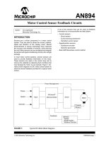
Motor control sensor feedback circuits
... signal-conditioning circuitry into a single package. In most motor control systems, several sensors are used to provide feedback information on the motor. These sensors are used in the control loop ... conditions that may damage the motor. As an example, Figure 1 pro- vides a block diagram of a DC motor control system to show the sensor feedback provided for a typical motor control. A list of the sensors ... efect tachometer • Back EMF/Sensorless control method FIGURE 1: Typical DC Motor Block Diagram. Author: Jim Lepkowski Microchip Technology Inc. Power Management Input Microcontroller Driver Motor Feedback Torque Speed Direction Current Sensor Sensors *...
Ngày tải lên: 03/01/2014, 18:55
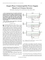
Single phase uninterruptible power supply based on z source inverter
... the capacitor volt- age of the Z-source inverter drops significantly as well; thus, the voltage difference between the reference u ∗ C and the actual capacitor voltage u C is sent to the PI controller ... 2007. [7] P. K. Jain, J. R. Espinoza, and H. Jin, “Performance of a single- stage UPS system for single- phase trapezoidal-shaped AC- voltage supplies,” IEEE Trans. Power Electron., vol. 13, no. 5, ... D. Lorenz, Control topology options for single- phase UPS inverters,” IEEE Trans. Ind. Appl., vol. 33, no. 2, pp. 493–501, Mar./Apr. 1997. [16] P. Mattavelli, “An improved deadbeat control for...
Ngày tải lên: 03/01/2014, 19:12


Chapter 9 unbalanced operation and single phase induction machines
... Free-acceleration characteristics of a capacitor-start single- phase induction motor. Figure 9.8-4. Average steady-state torque versus speed characteristics of a capacitor-start single- phase ... INDUCTION MACHINES 349 Open-Circuited Stator Phase For the purpose of analyzing an open-circuited stator phase, which is equivalent to single- phase operation, let us consider the stator circuits ... two- phase induction machine to be out of phase. To accomplish this the impedances of the stator windings are made unequal. For example, the split -phase machine is a two -phase induction motor...
Ngày tải lên: 16/02/2014, 18:48

Chapter 14 permanent magnet AC motor drives
... or nonsinusoidal back emf waveforms. Machines with sinusoidal back emfs may be controlled so as to achieve nearly con- stant torque; however, machines with a nonsinusoidal back emf may be less ... structure of the controls Figure 14.1-1. Permanent-magnet ac motor drive. Electrical System Command Signal Power Converter Control PM AM Mechanical System Sensors 566 PERMANENT-MAGNET AC MOTOR DRIVES ... particular, eventually, the back emf of the machine will rise to the point where the inverter cannot achieve the current command due to the fact that the back emf of the machine becomes too large....
Ngày tải lên: 16/02/2014, 18:54

Brushless DC Motor Control Made Easy potx
... DrivePort ; output to motor drivers return GetDrive movwf PCL ; computed goto OnTable retlw Invalid retlw Phase6 retlw Phase5 retlw Phase4 retlw Phase3 retlw Phase2 retlw Phase1 retlw Invalid SetTimer ... Notes: Sensorless brushless motor control * ; * ; Closed loop 3 phase brushless DC motor control. * ; Two potentiometers control operation. One potentiometer (A0) * ; controls PWM (voltage) and ... in Table 1. FIGURE 3: THREE PHASE BRIDGE To A -V M +V M A High control A Low control To B -V M +V M B High control B Low control To C -V M +V M C High control C Low control AN857 DS00857A-page...
Ngày tải lên: 30/03/2014, 07:20

motor control centers
... 47 Combination Motor Control Units Motor control centers principally contain combination motor control units. A combination motor control unit takes all the elements required to control an AC motor ... electric motors. Feeder Busway Motor Control Center Switchboard Panelboard Transformer Panelboard 480 VAC 480 VAC 480 VAC 120 VAC 480 VAC 480 VAC From Utility Outdoor Feeder Busway Basic Motor Control ... type of AC motor control, involves turning the motor on and off. This is often accomplished using a motor starter made up of a contactor and an overload relay. The contactor’s contacts are...
Ngày tải lên: 04/04/2014, 10:25

Single phase fully controlled rectifier
... a single phase fully controlled converter the _________ of an uncontrolled converters are replaced by ____________. ii) In a fully controlled converter the load voltage is controlled by controlling ... voltage harmonic in a single phase fully controlled bridge converter is _________ the input supply frequency. v) The input displacement factor of a single phase fully controlled bridge converter ... IIT, Kharagpur 23 10.2 Single phase fully controlled halfwave rectifier 10.2.1 Resistive load Fig.10. 1(a) shows the circuit diagram of a single phase fully controlled halfwave rectifier...
Ngày tải lên: 14/05/2014, 22:32

Single phase uncontrolled rectifier
... in the rectifier circuit. • Reaction of the rectifier circuit upon the ac network, reactive power requirement, power factor, harmonics etc. • Rectifier control aspects (for controlled rectifiers ... Displacement factor = Distortion factor = Power factor = 1.0 Version 2 EE IIT, Kharagpur 34 Version 2 EE IIT, Kharagpur 26 Fig 9.6 shows the circuit diagram and waveforms of a single phase ... resistive, inductive and capacitive loads will be discussed. Version 2 EE IIT, Kharagpur 8 Fig 9.2 shows the circuit diagram and the waveforms of a single phase uncontrolled half wave rectifier....
Ngày tải lên: 14/05/2014, 22:33
Bạn có muốn tìm thêm với từ khóa: