si ge randomly doped nanowires

Theoretical investigation on thermal properties of silicon based nanostructures
... model the Si- Ge bond, the length unit Si Ge is taken as the arithmetic average of individual 28 Chapter Simulation Methods Si and Ge parameters, while the energy unit Si Ge and Si Ge are taken ... 69 Tunable Thermal Conductivity of Si1 −x Gex Nanowires 75 3.1 76 3.2 Si/ Ge Randomly Doped Nanowires 77 3.3 Si/ Ge Superlattice Nanowires 82 3.4 Motivation ... bulk Si and SiNWs 74 3.1 Normalized thermal conductivity of Si1 −x Gex NWs versus Ge content at 300 K 79 3.2 Averaged phonon participation ratio versus Ge content in Si1 −x...
Ngày tải lên: 10/09/2015, 08:38
Spontaneous growth and luminescence of si siox core shell nanowires
... remain unchanged, suggesting that no other luminescent species were generated in the annealing process Conclusions Core-shell Si/ SiOx nanowires were prepared by a thermal evaporation of MoSi2 rods ... Chemical Physics Letters 378 (2003) 368–373 Fig Silicon (2p) and oxygen (1s) electron spectra for the Si/ SiOx nanowires Fig (a) SEM image of the as-prepared nanowires (b) EDX spectrum of the products ... crystalline silicon self-assembly Under the 488 nm excitation of an Arþ laser, the PL of the Si/ SiOx nanowires corresponds to Fig Photoluminescence spectra for the core-shell Si/ SiOx nanowires...
Ngày tải lên: 16/03/2014, 15:08
Báo cáo hóa học: " Relationship between structural changes, hydrogen content and annealing in stacks of ultrathin Si/Ge amorphous layers" docx
... http://www.nanoscalereslett.com/content/6/1/189 Page of Si: as-deposited Si: 350 C, hour Si: 350 C, hours 18 H conct [at%] 15 12 Ge: as-deposited Ge: 350 C, hour Ge: 350 C, hours 0,9 0,6 0,3 0,0 0,0 0,2 ... crystallization of silicon-germanium films Thin Solid Films 2005, 487:67 Abo Ghazala MS: Composition and electronic properties of a-SiGe:H alloys produced from ultrathin layers of a -Si: H/a -Ge: H Physica B ... 293:132 Frigeri C, Nasi L, Serényi M, Csik A, Erdélyi Z, Beke DL: AFM and TEM study of hydrogenated sputtered Si/ Ge multilayers Superlatt Microstruct 2009, 45:475 Frigeri AC, Serényi M, Csik A, Erdélyi...
Ngày tải lên: 21/06/2014, 05:20
Báo cáo hóa học: " Preface to Symposium E: Nanoscaled Si, Ge based Materials" potx
Ngày tải lên: 21/06/2014, 06:20

Báo cáo hóa học: " In situ Control of Si/Ge Growth on Stripe-Patterned Substrates Using Reflection High-Energy Electron " potx
... coverage already more than half a monolayer Ge is incorporated within the islands, assuming a Si/ Ge intermixing of xGe * 30% ripple spot specular spot 4.6ML 3D spot 5.2ML 6ML Ge coverage (ML) ... multichamber Si/ Ge molecular beam epitaxy and scanning tunneling microscopy system equipped with a Si e-beam evaporator, Ge effusion cell, and an Omicron variable temperature STM Stripe-patterned Si (001) ... 5nm Si at 450°C 10nm Si at 450°C (d) (e) (f) α=25° {113} 25nm Si at 450°C +2nm Si at 520°C α=9° {119} RHEED intensity (rel.units) Nanoscale Res Lett (2010) 5:1935–1941 18 nm at 520°C (g) Si buffer...
Ngày tải lên: 21/06/2014, 08:20

The composition dependent mechanical properties of ge si core–shell nanowires
... averaged bond lengths decrease with increasing the 2.50 Si Si Ge Ge Si Ge Bond length (Ang) 2.45 2.40 2.35 2.30 0.0 0.2 0.4 0.6 Composition 0.8 1.0 0.4 0.6 Composition 0.8 1.0 2.50 Si Si Ge Ge Ge Si ... of Si Si, Si Ge and Ge Ge in (a) Si- core /Ge- shell and (b) Si- core /Ge- shell nanowires as a function of composition Summary In summary, we calculate Young’s modulus of Ge- core/ Si- shell and Si- core /Ge- shell ... 1.0 2.50 Si Si Ge Ge Ge Si Bond length (Ang) 2.45 2.40 2.35 3047 composition in Si- core /Ge- shell nanowires, but increase with increasing the composition in Ge- core /Si- shell nanowires yet As speculated...
Ngày tải lên: 16/03/2014, 15:22

Báo cáo hóa học: " Kinetics of Si and Ge nanowires growth through electron beam evaporation" ppt
... in both Si and Ge NWs are quite similar can be attributed to the similar mechanism of surface diffusion of Si and Ge adatoms Page of vertically cut till the Si wafer substrate to make visible a ... the evaporation, by considering the different densities of Si and Ge 2D layers grown by EBE Differences between Si and Ge are very impressive In fact, the axial rate of Si NWs increases only at ... self-diffusion of Si [24] Moreover, the melting point of Ge is 475°C lower than that of Si, and solid-phase epitaxy regrowth in Ge has a lower activation energy (EGe = 2.0 eV) than in Si (ESi = 2.7...
Ngày tải lên: 21/06/2014, 05:20

Báo cáo "Preparation and characteristics of the In-doped ZnO thin films and the n-ZnO:In/p-Si heterojunctions for optoelectronic switch" potx
Ngày tải lên: 14/03/2014, 13:20

Deposition of carbon nanotubes on si nanowires by chemical vapor deposition
... image of the as-grown SiNWs Inset is a SAED pattern; (b) HREM image of a typical SiNW 50 Y.F Zhang et al / Chemical Physics Letters 330 (2000) 48±52 After the deposition, the color of the nanowires ... b-SiC and coated with a sheath of CNTs b-SiC nanowires and graphitic carbon, as shown in the top image in Fig 4b The characteristics of carbon deposition on the crystalline Si NW can be envisaged ... the nanowires was con®rmed to consist of a crystalline Si core and a silica outerlayer by using selectedarea electron diraction (SAED) pattern (inset of Fig 1a) and high resolution transmission...
Ngày tải lên: 16/03/2014, 15:04
High frequency FTIR absorption of sio2 si nanowires
... interface structure of the SiO2 /Si nanowires In SiO2 /Si nanowires, the interface between silicon core and SiO2 outer shell has a large ratio in the structure of nanowires body And there are ... amorphous SiO2 of silicon nanowires and in the interface between silicon crystal and amorphous SiO2 However, the detailed structural features of the surface of silicon nanowires with an amorphous SiO2 ... known that the SiO2 outer shell reacts with molten silicon, especially on the interface between SiO2 outer layer and silicon core during the formation of silicon nanowires [12] The oxygen in turn...
Ngày tải lên: 16/03/2014, 15:05
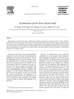
Si nanowires grown from silicon oxide
... decompositions of silicon oxide at the relatively low temperature of 9308C as shown below Si xO ™ Si xy1 q SiO Ž x ) and 2SiO ™ Si q SiO These decompositions result in the precipitation of silicon ... spectra taken from the as-grown Si nanowires, SiO and fully oxidized Si nanowires Žb PL spectra taken from the as-grown Si nanowires, SiO and fully oxidized Si nanowires tion The nuclei formed ... evaporation, Si Fig Ža TEM image showing the morphology of Si nanowires synthesized by the evaporation method Žb – Žd Nucleation stage of the Si nanowires N Wang et al.r Chemical Physics Letters...
Ngày tải lên: 16/03/2014, 15:08
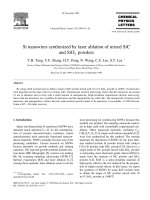
Si nanowires synthesized by laser ablation of mixed sic and sio2 powders
... one-dimensional growth of b-SiC can not be achieved Conclusions We have synthesized Si nanowires from SiC powders mixed with SiO powders which are used to synthesize single crystalline silicon ... set consists of the Ž111., Ž220 and Ž311 peaks of Si which are from the SiNWs The other set consists of the Ž111., Ž220 and Ž311 peaks of b-SiC which are from the b-SiC nanoparticles The positions ... attach Si nanowires The inset is SAED pattern Žb HRTEM image of the b-SiC nanoparticles The fringes are Ä1114 lattice planes with a spacing of 0.25 nm found in the SiNWs products by using other...
Ngày tải lên: 16/03/2014, 15:08
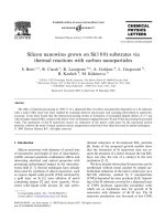
Silicon nanowires grown on si(1 0 0) substrates via thermal reactions with carbon nanoparticles
... formation of Si nanowires by thermal evaporation of pure SiO [23] or mixed Si SiO2 [24] powders Similarly, in our case a possible reaction route leading to the nucleation of the Si nanostructures ... decomposition of silicon monoxide 2SiO ! Si þ SiO2 at 1050 °C followed by the precipitation of Si atoms which are expelled from the mixture as crystalline nanowires A direct reduction of the SiO2 ... processed images, respectively (b) Si 2p and C 1s core level spectra taken inside (upper) and outside (lower) ÔsquaresÕ The Si 2p image in Fig reveals the growth of a relatively large structure,...
Ngày tải lên: 16/03/2014, 15:08
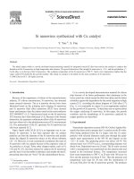
Si nanowires synthesized with cu catalyst
... the formation of Si nanowires The cheap Cu catalyst and the low growth temperature are favorable to the mass synthesis of the Si nanowires Conclusion Acknowledgements The Si nanowires could be ... low magnification TEM image of the Si nanowires Some silicon particles are mixed with the Si nanowires A straight nanowire 30 nm wide, a typical diameter for the thin Si nanowires is shown in Fig ... nanowires is similar to the size of the CuSi alloy nanoparticles So the tip of the Si nanowires is polyhedron, not the ball-like tip with η″-Cu 3Si alloy tips VS growth mechanism should be responsible...
Ngày tải lên: 16/03/2014, 15:12
Ultrafast growth of single crystalline si nanowires
... energetically favored site for the adsorption fusing Si nanoparticles of solid-phase reactants, to function as Si reservoir by eutectic liquid formation, and to become supersaturated with Si The ... surface of SiNWs was immediately oxided [11] and meanwhile the Si inside was melted and subsequently evaporated leaving a SiO2 tube [2] Propose mechanism The formation mechanism of nanowires generally ... growth of fabrication Conclusion In summary, Si nanowires were catalytically synthesized by calcining Si nanopowder containing Fe(NO3)3 in an H2 A pathway of the growth of SiNWs was presented based...
Ngày tải lên: 16/03/2014, 15:13
Characteristics of siox nanowires synthesized via the thermal heating of cu coated si substrates
... possibly from the substrate TEM shows the general morphology and dimension of SiOx nanowires Figs 2a and b show the TEM images of the product, indicating that this raw material indeed consists ... nanowire stem consists of Si and O (Fig 2d) Au signals are generated from the gold grid on which these nanowires were supported EDX spectrum on the wire tip shows the signals of Si, O, Au, and ... TEM images showing the general morphology of SiOx nanowires (Arrow 1: helical nanowires or nanosprings; Arrow 2: nanoparticles) The lower right inset of (a) is the SAED pattern of SiOx nanowires...
Ngày tải lên: 16/03/2014, 15:14
Dimensional evolution of silicon nanowires synthesized by au–si island catalyzed chemical vapor deposition
... the Si- NWs were characterized by using a field emission scanning electron microscopy (FESEM) for a 301 tilted view and cross-sectional geometries The dimensions of the Au Si islands and the Si- NWs ... increases, dissolution of more Si into Au Si droplets will lead to increasing Si chemical potential in the liquid droplets with a relationship of DmSi ¼ kT ln p, where DmSi is Si chemical potential in ... Au Si droplet is more dominant than lateral growth rate Conclusion We studied the morphological and dimensional evolution of the Si- NWs on Si (0 1) and (1 1) surfaces grown 157 by using Au–Si...
Ngày tải lên: 16/03/2014, 15:15
Formation of silicon oxide nanowires directly from au si and pd–au si substrates
... of Au /Si and Pd–Au /Si substrates at 1100 1C Fig shows FE-SEM images of SiOx nanowires grown on Au /Si and Pd–Au /Si substrates, as well as an EDX spectrum of SiOx nanowires grown on the Au /Si substrate ... the SiOx nanowires formed on the Pd–Au /Si substrate is nearly consistent with the of SiO2, indicating the formation of SiO2 nanowires on the Pd–Au /Si substrate at this growth temperature Since ... Results and discussion Fig shows FE-SEM images revealing the general morphologies of the thermally heated Au deposited Si (0 1) [Au /Si] and Pd–Au deposited Si (0 1) [Pd–Au /Si] substrates in the...
Ngày tải lên: 16/03/2014, 15:16

Investigation of au and in as solvents for the growth of silicon nanowires on si(1 1 1)
... 900 600 300 0 0.2 0.2 0.4 0.6 mole Si/ (Si+ In) 0.8 0.4 0.8 1500 T (C) 1200 900 600 300 0.6 mole Si/ (Si+ Au) Fig Binary phase diagrams; top: In Si and bottom: Au Si Since the state of the substrate ... absence of nanowires by considering the surface tension of indium and the low solubility of silicon in indium Iacopi et al [18] also studied indium as solvent for CVD growth of silicon nanowires ... did not get any nanowires Consequently, nanowire growth, at least under our experimental conditions, is only possible on Fig SEM image of a sample with gold as solvent after silicon deposition...
Ngày tải lên: 16/03/2014, 15:17
Multilevel modeling of the influence of surface transport peculiarities on growth, shaping, and doping of si nanowires
... onto a single, randomly selected empty surface site [8] (ii) A diffusion jump of a randomly selected adatom in a random direction for some distance l (the distance between the nearest sites) ... Physica E 40 (2008) 2446–2453 2449 /tS depends on the system size R and the diffusion coefficient Deff exactly like the quasi-steady-state diffusion time (QSSDT) does [11] in an ordinary diffusion ... sites) during a time step t if there is a free site In a general case, an irreversible diffusion of the selected adatom into the catalyst bulk may be considered This will be done in the framework...
Ngày tải lên: 16/03/2014, 15:18