learning autocad 2010 volume 2 engineering surveyor

Learning AutoCAD 2010, Volume 2 phần 1 potx
... Architectural 21 2 Challenge Exercise: Mechanical 21 4 Chapter Summary 21 7 Chapter 10: Working with Reusable Content 21 9 Lesson: Using Blocks 22 0 About Blocks 22 1 How Blocks Behave 22 4 Creating Blocks 22 6 Inserting ... Preparation 001B1-050000-CM01A April 20 09 Learning A utoCAD đ 20 10, Volume 2 Using hands-on exercises, learn the features, commands, and techniques for creating, editing, and printing drawings with AutoCAD đ 20 10 and AutoCAD ... Splines 27 2 Creating Splines 27 4 Exercise: Create a Spline 28 0 Lesson: Creating Ellipses 28 2 About Ellipses 28 3 Creating Ellipses 28 4 Exercise: Create Ellipses 28 8 Lesson: Using Tables 29 0 About...
Ngày tải lên: 09/08/2014, 11:20

Learning AutoCAD 2010, Volume 2 phần 2 pdf
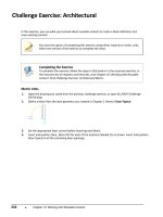
... Challenge Exercise: Mechanical ■ 39 2. Create a new layout configuration with the following settings: ■ DWF6 ePlot.pc3 ■ ISO A3 ( 420 x 29 7) ■ Three viewports that do not show on the ... changed in Layout2: ■ Click the Model tab. Confirm that the furniture color remained brown. ■ Click the Layout1 tab. Notice that the furniture color remained brown. ■ Click the Layout2 tab. Confirm ... I_ARCH-Challenge- CHP06.dwg. 2. Configure Layout1 to plot with the following settings: ■ Orientation: Landscape ■ Scale: 1:1 ■ Printer/Plotter: DWF6 ePlot.pc3 ■ Paper size: ARCH expand D (36.00 x 24 .00 Inches) ...
Ngày tải lên: 09/08/2014, 11:20


Learning AutoCAD 2010, Volume 1 phần 2 doc
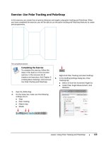
... absolute coordinates. To do so, enter a pound sign before the first coordinate, for example, #2, 20. If you enter 2, 20 (without the # sign), the point will be relative to the last selected point. The dynamic ... drawing window for the first point (1). ■ Enter the polar coordinate @2& lt;45 (2) . Press ENTER. ■ Enter the polar coordinate @2& lt;135 (3). Press ENTER. ■ Enter c for the close option. Press ... new circle. Specify radius of circle or [Diameter] < ;25 .000>: Press ENTER to create a new circle with a 25 unit radius. 68 ■ Chapter 2: Creating Basic Drawings Practice Exercise: Line Command ...
Ngày tải lên: 09/08/2014, 11:20

Learning AutoCAD 2010, Volume 1 phần 1 ppt
... Objects 20 5 Mirroring Objects 20 6 Exercise: Mirror Objects in the Drawing 21 2 Lesson: Creating Object Patterns 21 4 Creating an Array of Objects 21 5 Exercise: Array Objects in the Drawing 22 3 Lesson: ... Object's Size 22 8 Scaling Objects 22 9 Exercise: Scale Objects Using the Copy Option 23 4 Challenge Exercise: Grips 23 6 Challenge Exercise: Architectural 24 3 Challenge Exercise: Mechanical 24 8 Chapter ... Properties 27 3 About Object Properties 27 4 ByLayer Property 27 7 Changing Object Properties 27 9 Exercise: Change Object Properties 28 8 Lesson: Quick Properties 29 1 About Quick Properties 29 2 Using...
Ngày tải lên: 09/08/2014, 11:20

Learning AutoCAD 2010, Volume 1 phần 3 docx
... Press F2. ■ Observe that @ symbol was automatically added to the coordinate making it relative to the last point you selected. ■ Practice making the following rectangles: ■ 2 x 2 (enter 2, 2) ■ ... UNDO Menu Bar: Edit > Undo Quick Access Toolbar: Undo 122 ■ Chapter 2: Creating Basic Drawings 3. Begin creating geometry such as lines or polylines. Click ... overrides are needed. 9. Close all files. Do no not save. 94 ■ Chapter 2: Creating Basic Drawings 12. To draw a line perpendicular to the last: ■ Drag the cursor downward, making...
Ngày tải lên: 09/08/2014, 11:20
Learning AutoCAD 2010, Volume 1 phần 4 docx
... section in the Introduction in Volume 1. 146 ■ Chapter 2: Creating Basic Drawings 4. For the next point: ■ Move the cursor down and to the right. ■ Enter 2& apos;4 .25 . Press TAB. Enter 45. ... inches if no symbol is typed. Example 16' -2& quot; can be simply typed: 16&apos ;2 ■ When using Architectural units, you may type 16' -2& quot; or the equivalent in inches: 194 ■ If you ... can use both the Implied Window and Implied Crossing methods while holding down SHIFT. 126 ■ Chapter 2: Creating Basic Drawings 4. On the Snap and Grid tab: ■ Click PolarSnap. ■ Enter...
Ngày tải lên: 09/08/2014, 11:20
Learning AutoCAD 2010, Volume 1 phần 5 pptx
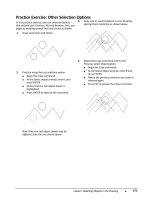
... 5. Enter Y to erase source objects or N to keep the source objects. 21 2 ■ Chapter 3: Manipulating Objects Exercise: Mirror Objects in the Drawing In this exercise, ... what you enter for the new angle. For instance, if point (2) was selected before point (1), the new angle would have been 180. 20 6 ■ Chapter 3: Manipulating Objects Mirroring Objects ... select the objects. ■ Right-click one of the grips (1). Click Mirror (2) . ■ Right-click again. Click Copy (3). 1 82 ■ Chapter 3: Manipulating Objects Exercise: Move Objects In...
Ngày tải lên: 09/08/2014, 11:20
Learning AutoCAD 2010, Volume 1 phần 6 doc
... cannot be renamed or deleted. AutoCAD uses that layer to establish predictable behaviors for objects such as blocks, regardless of how other layers are named. 22 2 ■ Chapter 3: Manipulating ... M_MECH-Challenge- CHP03.dwg. 2. Rotate the right side view 90 degrees as shown. Note: The views in the image are closer together than they will appear in your drawing. 26 2 ■ Chapter 4: Drawing ... degrees. Your office layout should look like the following image. 24 2 ■ Chapter 3: Manipulating Objects 12. Use the Mirror and Copy grip modes to populate the next office area...
Ngày tải lên: 09/08/2014, 11:20
Learning AutoCAD 2010, Volume 1 phần 7 potx
... able to: ■ Use the Properties palette to adjust object properties. 28 2 ■ Chapter 4: Drawing Organization and Inquiry Commands 2. On the Home tab, click Layers panel > Layer Control list. ... you may add more geometry to any locked layer. Lesson: Changing Object Properties ■ 28 3 2. On the ribbon, click Home tab > Properties panel > Object Color. Select the desired ... current and draw rectangles. ■ Click the Line layer to make it current and draw lines. 29 2 ■ Chapter 4: Drawing Organization and Inquiry Commands About Quick Properties The Quick...
Ngày tải lên: 09/08/2014, 11:20

Learning AutoCAD 2010, Volume 1 phần 8 pot
... between circles 2 and 4 = 105. 629 6 mm 11. Angle = 131 degrees Delta Y = 44. 927 5 mm 13. X = 25 3.1353Y = 0.0000Z = 0.0000 14. Net area = 24 255.3940 mm 3 42 ■ Chapter 4: ... Volume Measures the volume of an object or a defined area. There are also options to keep a running total as you define volume or to subtract specified regions from total calculated volume. ... the Volume tool you may turn on the Add or Subtract mode and either keep a running total of volume as you define regions or subtract a specified region from the total volume. ■ When using the Volume...
Ngày tải lên: 09/08/2014, 11:20

Learning AutoCAD 2010, Volume 1 phần 9 pot
... Join Objects. 1. Open M_Join-Objects.dwg. 2. Mirror a door from the right side of the room to the left side. Use the Mid Between 2 Points object snap to obtain the midpoint of the ... join (2) . ■ Press ENTER to complete the command. 5. To Join the arc segments and close them. Method 1: ■ Begin the Join command. ■ Select one arc (1) then select the other (2) . ■ ... lower left view (1). ■ When prompted for the through point, select the point on the top-left view (2) . ■ Press ENTER to exit the Offset command. 15. Use the Offset command with the...
Ngày tải lên: 09/08/2014, 11:20
Learning AutoCAD 2010, Volume 1 phần 10 pot
... M_Stretch-Objects.dwg. 2. On the status bar, turn Osnap off. 3. To add 20 00 units to the left side of the structure: ■ On the Modify panel, click Stretch. ■ Click point (1) then point (2) to define ... Stretch command. 2. Select the objects to be stretched by defining a crossing window or crossing polygon selection. 3. Select the base point for the stretch. 422 ■ Chapter 5: ... 1. Draw a rectangle. 2. To Fillet a single corner: ■ Begin the Fillet command. ■ Enter R and press ENTER. ■ Specify a fillet radius of .25 and press ENTER. ■ Click the lines...
Ngày tải lên: 09/08/2014, 11:20
Bạn có muốn tìm thêm với từ khóa: