fundamentals of digital logic design by floyd pdf


fundamentals of digital logic and microcomputer design
... given by Equation 2.2. The right-hand side of Equation 2.3 is represented by the form of equation 2.1, where b=10,d,=1,d,=2,do=5,d -,= = d_,=O,p=3,andq=0. 23 Fundamentals of Digital Logic ... from a basic point of view. Logic- level design is the design tech- nique in which logic gates are used to design a digital component such as an adder. Final- ly, system-level design is covered ... Motorola 68030168040/68060/PowerPC 14 TABLE 1.2 Fundamentals of Digital Logic and Microcomputer Design Comparison of output characteristics of LS-TTL, nMOS, HC, and HCT IOH VOL IOL LS-TTL...
Ngày tải lên: 01/06/2014, 10:12

Tài liệu National Instruments - Fundamentals of Digital Electronics pdf
... 2-2. Dot Arrangement Used in Dice Codes By turning on the appropriate lights, you can create any of the six patterns on the face of a die. Fundamentals of Digital Electronics 1-2 â National Instruments ... counters, in the generation of harmonic clock subfrequencies, and in many higher order functions such as digital- to-analog and analog-to -digital devices. Fundamentals of Digital Electronics 3-6 â ... Instruments Corporation 5-5 Fundamentals of Digital Electronics 8-Bit Pseudo-Random Number Generator The addition of an analog-to -digital converter allows the parallel outputs of the pseudo-random...
Ngày tải lên: 25/01/2014, 13:20
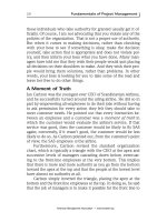
Fundamentals of Project Management Worksmart by James P. Lewis_3 pdf
Ngày tải lên: 21/06/2014, 08:20


Student Solutions Manual containing selected solutions to Fundamentals of Machine Component Design pdf
Ngày tải lên: 27/06/2014, 08:20

Juvinall, Marshek - Fundamentals of Machine Component Design, 3rd ed - Student Solutions Manual Episode 3 pdf
Ngày tải lên: 12/08/2014, 16:20

Fundamentals of RF Circuit Design With Low Noise Oscillators
... lasting designs. The book is an extension of the course material provided to delegates on advanced one-week intensive courses offered to industry by the University of York. These are offered ... defects in the software. Designations used by companies to distinguish their products are often claimed as trademarks. In all instances where John Wiley & Sons, Ltd is aware of a claim, the ... writing of the Publisher, with the exception of any material supplied specifically for the purpose of being entered and executed on a computer system, for exclusive use by the purchaser of the...
Ngày tải lên: 08/04/2013, 10:50
LabView - Engineering Fundamentals of Digital Electronics
... fundamental building blocks of digital logic circuitry. These devices function by “opening” or “closing” to admit or reject the passage of a logical signal. From only a handful of basic gate types ... Corporation 6-3 Fundamentals of Digital Electronics Binary Counters Binary counters are formed from J-K flip-flops by tying all the (J,K) inputs to a logic 1 (HI) and connecting the output of each flip-flop ... are also “on.” In digital electronics, the on state is often represented by a 1 and the off state by a 0. The relationship between the input signals and the output signals is often summarized...
Ngày tải lên: 19/10/2013, 11:15

Tài liệu Fundamentals of Digital Electronics doc
... Instruments Corporation 1-1 Fundamentals of Digital Electronics Lab 1 Gates Gates are the fundamental building blocks of digital logic circuitry. These devices function by “opening” or “closing” ... Counter.vi. Clock QD Q QD Q QD Q QD Q Q 1 Q 2 Q 3 Q 4 Fundamentals of Digital Electronics 7-6 â National Instruments Corporation Lab 7 Digital- to-Analog Converter Figure 7-6. Output of a 4-Bit, 6-Bit, and 8-Bit DAC As the number of bits of ... are A and B, the output (often called Q) is “on” only if both A and B are also “on.” In digital electronics, the on state is often represented by a 1 and the off state by a 0. The relationship...
Ngày tải lên: 13/12/2013, 01:15

Tài liệu Fundamentals of Digital Manufacturing Science pptx
... ideas and new methods are endless. The concepts of digital library, digital valley, digital home, digital enterprise, digital economy and even digital earth’, which is the common framework used ... The characteristics of digital equipment embody the digitali- zation of movement, including the digital modeling of the driving process, motion planning under the conditions of multiple restrictions, ... positive design, reverse engineering and integration of positive design and reverse engineering, but these methods can only make the geometric information of product digital [16]. A key feature of...
Ngày tải lên: 21/02/2014, 22:20

Fundamentals of Digital Manufacturing Science potx
... fields of digital manufacturing. 2.1.1 Operation Reference Mode of Digital Manufacturing System The basic process of the digital manufacturing means that the design, simulation and production of ... the digitalization of the systems, including a variety of digital technologies and digital- manufacturing-oriented resources and the environment technologies in the whole lifecycle of the digital ... and knowledge. Digitalization is the basis and the core of the informatization of the system. The specific targets of informatics are the things dominated by the 1.3 Connotation and Research Method of Digital...
Ngày tải lên: 08/03/2014, 17:20

Fundamentals of Operative Dentistry: A Contemporary Approach pdf
Ngày tải lên: 15/03/2014, 12:20

Digital logic design
... Computer Engineering ECE380 Digital Logic Introduction to Logic Circuits: Design Examples Dr. D. J. Jackson Lecture 5-2Electrical & Computer Engineering Design examples ã Logic circuits provide ... AND logical AND –OR logical OR – NOT logical NOT – NAND, NOR, XOR, XNOR (covered later) ã Assignment operator <= A variable (usually an output) should be assigned the result of the logic ... switches ã Capable of implementing logic functions of millions of equivalent gates 2 Dr. D. J. Jackson Lecture 13-3Electrical & Computer Engineering Transistor switches ã Logic circuits are...
Ngày tải lên: 27/03/2014, 20:00
Bạn có muốn tìm thêm với từ khóa: