electrical protection and control devices


Practical Troubleshooting of Electrical Equipment and Control Circuits pptx
Ngày tải lên: 07/03/2014, 08:20

Aircraft Flight Dynamics Robert F. Stengel Lecture16 Aircraft Control Devices and Systems
Ngày tải lên: 04/07/2014, 19:28

Open distributed automation and control with iec 61499.pdf
... OPEN DISTRIBUTED AUTOMATION AND CONTROL WITH IEC 61499 JHC/2001-04-03 p. 18 Open Distributed Automation and Control with IEC 61499 Open Distributed Automation and Control with IEC 61499 ã Background ã ... Distributed Automation and Control with IEC 61499 Open Distributed Automation and Control with IEC 61499 ã Background ã Architecture ã Object Models ã Software Tool Requirements ã Status and Future OPEN ... #1 Simulation Machine Control Machine Control OPEN DISTRIBUTED AUTOMATION AND CONTROL WITH IEC 61499 JHC/2001-04-03 p. 13 Event and Data Interfaces Event and Data Interfaces Data outputsData...
Ngày tải lên: 20/08/2012, 11:15

Mechanisms and Mechanical Devices Sourcebook - Chapter 3
... hardened steel stop on the clutch control shaft. A spiral spring then impels the clutch control shaft to rotate clockwise. That movement throws out the clutch and applies the brake. The initial movement ... the raising and lowering of the transport is accomplished by a cam. The shafts, F, E, and D are positioned by the frame of the machine. Special bell cranks support the transport and are interconnected ... those that keep both of the operator’s hands occupied on controls away from the work area to shields that completely enclose the work in progress on the machine and prevent machine operation unless...
Ngày tải lên: 22/10/2012, 14:26

Mechanisms and Mechanical Devices Sourcebook - Chapter 4
... every lobe on gear 4, and T 3 /T 4 = L 3 /L 4 = 2/3, where T 3 and T 4 are the numbers of teeth on gears 3 and 4. T 1 and T 2 will denote the numbers of teeth on gears 1 and 2. Next, select the ... number of lobes L 3 and L 4 on the gears 3 and 4. In the drawings, L 3 = 2 and L 4 = 3. Any two lobes on the two gears (i.e., any two lobes of which one is on one gear and the other on the ... near standstill. In the disengaged position, the angu- lar velocity ratio between the output and input shafts (the “gear” ratio) is entirely dependent upon the design angles α and β and independent...
Ngày tải lên: 22/10/2012, 14:26

Mechanisms and Mechanical Devices Sourcebook - Chapter 5
... 138 134 TWELVE EXPANDING AND CONTRACTING DEVICES Parallel bars, telescoping slides, and other devices that can spark answers to many design problems. Fig. 1 Figs. 1 and 2 Expanding grilles are ... turns. Dynamic and static balancing is simplified when an expanding wheel is attached to a nonexpanding main wheel. As a pulley, an expanding wheel can have a steel band fastened to only one section and ... and 4; two-jointed inter- mediate links: links 5 and 7; three jointed intermediate links: link 6. The input motions to be added are a and b; their sum s is equal to c 1 a + c 2 b, where c 1 and...
Ngày tải lên: 22/10/2012, 14:26

Mechanisms and Mechanical Devices Sourcebook - Chapter 6
... ARRANGEMENTS Differential, duplex, and other types of screws can provide slow and fast feeds, minute adjustments, and strong clamping action. Rapid and slow feed. With left- and right-hand threads, slide motion ... non-sliding, non- rolling radial and axial support without the need for lubrication. The design com- bines high radial and axial stiffness with a relatively low and controlled angular stiffness. ... and neg- ligible hysteresis characteristics. The bearing is radiation-resistant and can be used in high vacuum conditions or in environments where there is dirt and contamination. 185 TAUT BANDS...
Ngày tải lên: 22/10/2012, 14:26

Mechanisms and Mechanical Devices Sourcebook - Chapter 7
... conveying, and elevating. STANDARD ROLLER CHAIN—FOR POWER TRANSMISSION AND CONVEYING SINGLE WIDTH—Sizes 5 ⁄ 8 in and smaller have a spring-clip connect- ing link; those 3 ⁄ 4 in and larger ... input and output of the simple windlass. Control and output ends of the mul- titurn bands are both connected to gears mounted concentrically with the drum axis. When the servomotor rotates the control ... cycloidal is considered to be the best standard cam contour because of its low dynamic loads and low shock and vibration characteristics. One reason for these outstanding attributes is that sud- den...
Ngày tải lên: 22/10/2012, 14:26

Mechanisms and Mechanical Devices Sourcebook - Chapter 8
... motor com- parable in size and power to those used in standard reel-to-reel recorders, and a large bi-peripheral flywheel and sturdy capstan that reduces wow and flutter and drives the tape. A patent ... manufac- turing and alignment and (2) thermal and vibrational changes in the sizes and posi- tions of the meshing components. One of the benefits is a reduction of gear-tooth- contact noise and vibration. ... models while thin rubber bands and pulleys are employed in con- ventional portable recorders. Take-up and rewind. In the new tape drive system, the flywheel drives the take- up and rewind spindle....
Ngày tải lên: 22/10/2012, 14:26

Mechanisms and Mechanical Devices Sourcebook - Chapter 9
... requirements of MIL-E-5400, class 3 and MILK-3926 specifications. Applications were seen in counter and reset switches and controls for machines and machine tools, radar systems, and precision potentiometers. Eight-Joint ... Page 317 336 LINKAGES FOR BAND CLUTCHES AND BRAKES Fig. 1 An outside band clutch operated by a roller and cone. Fig. 2 An outside band clutch made as two half wrap bands with an interme- diate ... faster. Edges of the clutch bands carry the entire load, and there is also a compound action of one band upon another. As the torque builds up, each band pushes down on the band beneath it, so each...
Ngày tải lên: 22/10/2012, 14:26

Mechanisms and Mechanical Devices Sourcebook - Chapter 10
... two separate con- trollers and actuators. The first controls the in-feed speed and tension of the paper stock, and the second controls the wind-up. The in-feed is controlled by maintain- ing ... that is sound and slip-free. An automatic, constant- 350 Speed and Tension Control (continued) Fig 4 Floating rolls are direct indicators of speed and tension in the paper web. Controller- actuators ... movements actuate conveyor control mechanisms. Sclater Chapter 10 5/3/01 1:07 PM Page 350 tension winding control and a secondary indicator initiate the control action. The control system shown in...
Ngày tải lên: 22/10/2012, 14:26

Mechanisms and Mechanical Devices Sourcebook - Chapter 11
... opening or closing the electrical circuit that controls a heat- ing or cooling unit. It is adjustable and resistant to shock and vibra- tion. Its range is 100 to 1500°F, and it responds to a temperature changes ... single-gland type. Automatic wear control compensates for normal wear and maintains volumetric efficiency. This pump will handle 5 to 300 gph without churning or foaming. It needs no lubrication and ... POWER Cartridge-actuated devices generate a punch that cuts cable and pipe, shears bolts for fast release, and provides emergency thrust. Sclater Chapter 11 5/3/01 1:17 PM Page 402 Fig. 1 Automatic weighing and...
Ngày tải lên: 22/10/2012, 14:26

Mechanisms and Mechanical Devices Sourcebook - Chapter 13
... ψ 13 and ψ 12 . This establishes points A′ 2 , A′ 3 and A′ 4 , but here A′ 3 and A′ 4 coincide because of symmetry of A 3 and A 4 about A 0 B 0 . 4. Draw lines A 1 A′ 2 and A 1 A′ 4 , and the ... example, in Fig. 1 two angular motions, φ 12 and φ 13 , must be synchronized with two others, ψ 12 and ψ 13 , about the given pivot points A 0 and B 0 and the given crank length A 0 A. This means ... ψ 13 , and ψ 14 , using freely chosen pivot points A 0 and B 0 . In this case, crank length A 0 A as well as B 0 B is to be determined, and the procedure is: 1. Locate pivot points A 0 and B 0 on...
Ngày tải lên: 22/10/2012, 14:26

Mechanisms and Mechanical Devices Sourcebook - Chapter 14
... capability and verifying commercial demand. Initially ADI built these devices by interleaving, com- bining, and customizing its internal manufacturing processes to produce the micromechanical devices ... organic and freeform shapes. Consequently, commercial software producers offer 3D hybrid surface and solid-modeling suites that integrate 2D drafting and 3D wireframe with 3D surface and 3D solid ... that were required are removed, and the model’s surfaces are sanded or polished. Polymers such as urethane acrylate resins can be milled, drilled, bored, and tapped, and their outer surfaces can...
Ngày tải lên: 22/10/2012, 14:26
Mechanisms and Mechanical Devices Sourcebook - Chapter 15
... Technologies Group, Radford, VA ã Ledex Actuation Products, TRW Control Systems, Vandalia OH ã Sandia National Laboratories, Sandia Corporation, Albuquerque, NM ã SolidWorks Corporation, Concord, ... Data Sclater, Neil. Mechanisms and mechanical devices sourcebook / Neil Sclater, Nicholas P. Chironis.— 3rd ed. p. cm. Rev. ed of: Mechanisms & mechanical devices sourcebook / [edited by] ... applications beyond NASA’s immediate objectives in space science and requirements for specialized equip- ment. The names of the scientist/inventors and the NASA facilities where the work was performed have...
Ngày tải lên: 22/10/2012, 14:26

Mechanisms and Mechanical Devices Sourcebook - Chapter 12
... upward an additional 15º, locking the handle cam and the slide. In step 6, the handle is rotated an additional 30º, forcing the box and the mating spring-loaded electrical con- nectors downward so ... left-handed threads, ã An eye on a shank with external right- handed threads, and ã A flanged collar with left-handed external threads to mate with the shank of the first- mentioned eye, and right-handed ... slot in the rail and engages the rail roller. In step 4, the handle is rotated upward 75º, forcing the box 410 rearward to mate with the electrical connectors. In step 5, the handle is pushed...
Ngày tải lên: 22/10/2012, 14:26
Mechanisms and Mechanical Devices Sourcebook - Chapter 16
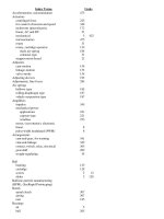
... angular-momentum-balanced, robot 48 ball -and- cone 250 ball -and- disk, and 251 ball -and- screw 5 12 bearings and roller 117 belt 12 224 257 belt -and- chain, variable speed 224 cam for ... 158 ring gear and slider 450 ring and slider, Jenson’s 450 robot 34 rocker arm and disk 123 roller-dwell 119 rotary, short-dwell 112 rotary-to-reciprocating motion and dwell 116 ... disk, and 249 double 249 roller, and 249 speed 318 spherical 249 ball -and- cone 250 crank 167 disk, with 249 slide oscillator 168 tilting-ball 249 swivel-gear 282 tension controlling...
Ngày tải lên: 22/10/2012, 14:27
