discrete fourier transform and signal spectrum

Real-Time Digital Signal Processing - Chapter 7: Fast Fourier Transform and Its Applications
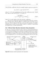
... 7.1 Twiddle factors for DFT, N case 306 FAST FOURIER TRANSFORM AND ITS APPLICATIONS The inverse discrete Fourier transform (IDFT) is used to transform the X(k) back into the original sequence ... increase the signal length from L to N by appending N À L zero samples to the tail of the signal To compute the spectrum of an analog signal digitally, the signal is sampled first and then transformed ... sequence mk by m samples are a linear shift of X(k) by WN DISCRETE FOURIER TRANSFORM 311 DFT and z -transform Consider a sequence x(n) having the z -transform X(z) with an ROC that includes the unit circle...
Ngày tải lên: 28/10/2013, 05:15

The Discrete Fourier Transform
... Type of Transform 145 Example Signal Fourier Transform signals that are continious and aperiodic Fourier Series signals that are continious and periodic Discrete Time Fourier Transform signals ... are discrete and aperiodic Discrete Fourier Transform signals that are discrete and periodic FIGURE 8-2 Illustration of the four Fourier transforms A signal may be continuous or discrete, and ... term: transform, is extensively used in Digital Signal Processing, such as: Fourier transform, Laplace transform, Z transform, Hilbert transform, Discrete Cosine transform, etc Just what is a transform? ...
Ngày tải lên: 13/09/2012, 09:49
mathematics of the discrete fourier transform
... introduces the Discrete Fourier Transform (DFT) and points out the elements which will be discussed in this reader 1.1 DFT Definition The Discrete Fourier Transform (DFT) of a signal x may be ... a variety of practical spectrum analysis examples, using primarily Matlab to analyze and display signals and their spectra DRAFT of “Mathematics of the Discrete Fourier Transform (DFT),” by J.O ... telephone is bandlimited to 3kHz, and since bandlimited signals cannot be time limited, it follows that one cannot hang up the telephone” DRAFT of “Mathematics of the Discrete Fourier Transform (DFT),”...
Ngày tải lên: 31/03/2014, 15:21
The discrete fourier transform
... DT systems Now we focus on DT signals for a while The discrete Fourier transform or DFT is the transform that deals with a finite discrete- time signal and a finite or discrete number of frequencies ... aperiodic signals Discrete- time Fourier transform (DTFT) review Recall that for a general aperiodic signal x[n], the DTFT and its inverse is ∞ X (ω) = x[n] e−ωn , x[n] = n=−∞ 2π π −π X (ω) eωn dω Discrete- time ... most important transforms: continuous time: Laplace, Fourier, Fourier Series, discrete time: Z, DTFT, DTFS, DFT/FFT The first six are for pencil and paper analysis/intuition/understanding The DFT/FFT...
Ngày tải lên: 08/06/2014, 20:19
Báo cáo sinh học: " Research Article Eigenvectors of the Discrete Fourier Transform Based on the Bilinear Transform" potx
... Santhanam and J H McClellan, “The discrete rotational Fourier transform, ” IEEE Transactions on Signal Processing, vol 44, no 4, pp 994–998, 1996 [6] C Candan, M A Kutay, and H M Ozaktas, “The discrete ... second derivative and the Fourier transform operators in (3) with the matrix given in (16) and the DFT matrix, − Proof As B1 and E2 are both circulant and symmetric, B1 E2 is symmetric and circulant ... fractional Fourier domains,” IEEE Transactions on Signal Processing, vol 45, no 5, pp 1129–1143, 1997 [3] X.-G Xia, “On bandlimited signals with fractional Fourier transform, ” IEEE Signal Processing...
Ngày tải lên: 21/06/2014, 16:20

báo cáo hóa học:" Discrete fourier transform-based TOA estimation in UWB systems" potx
... transmitted and received signals and ⊗ the convolution operator In Figure 5, we show the baseband and passband 2 CRLBs (cbb and cpb ) of τ, the MSEs ( ∈τ bb and ∈ pb ) of ˜ k τk ˜ the global baseband ... local passband CRLB (resp the sum of the local baseband CRLB of f0 and fk) In Figure 4, we show the local baseband and passband CRLBs ( cbb , cpb ), and the MSEs of the local baseband k k k (17) ... (baseband) of the transmitted signal, the received signal and the AWGN, filtered around central frequency fc with a bandwidth B ([fc - B/2, fc + B/2]) r(t) can be written as: τ where a and τ...
Ngày tải lên: 21/06/2014, 17:20
báo cáo hóa học:" Research Article Pitch- and Formant-Based Order Adaptation of the Fractional Fourier Transform and Its Application to Speech Recognition" pptx
... Radon-Wigner transform, and the Fractional Fourier transform Fractional Fourier transform, as a new time-frequency analysis tool, is attracting more and more attention in signal processing literature ... chirplike signals [16] Several approaches to modeling speech or audio signals as chirp-like signals have been studied [17–19] In [20], chirped autocorrelations and the fractional Fourier transform ... fractional fourier transform and timefrequency representations,” IEEE Transactions on Signal Processing, vol 42, no 11, pp 3084–3091, 1994 [16] L Qi, R Tao, S Zhou, and Y Wang, “Detection and parameter...
Ngày tải lên: 21/06/2014, 20:20
Báo cáo hóa học: " Research Article Fast Discrete Fourier Transform Computations Using the Reduced Adder Graph Technique" pptx
... Graumann, and L Turner, “Implementation of fast Fourier transforms and discrete cosine transforms in FPGAs,” in Proceedings of the 5th International Workshop on Field-Programmable Logic and Applications ... K Shenoi, and A Peterson, “Quadratic residues: application to chirp filters and discrete Fourier transforms,” in Proceedings of IEEE International Conference on Acoustics, Speech, and Signal Processing ... Rader, Discrete Fourier transform when the number of data samples is prime,” Proceedings of the IEEE, vol 56, no 6, pp 1107–1108, 1968 [32] J McClellan and C Rader, Number Theory in Digital Signal...
Ngày tải lên: 22/06/2014, 23:20
Báo cáo hóa học: " Offline Signature Verification Using the Discrete Radon Transform and a Hidden Markov Model" doc
... signature and include the discrete Wavelet transform [7], the Hough transform [8], horizontal and vertical projections [9], and smoothness features [10] Local features are extracted at stroke and substroke ... writers, with between 15 and 20 genuine signatures per writer An average FRR and FAR of 3% and 9.8%, respectively is obtained Kaewkongka [8] uses the Hough transform (general Radon transform) to extract ... signatures, 10 casual forgeries, and 10 skilled forgeries per writer An FRR of 2.83% and an FAR of 1.44%, 2.50%, and 22.67% are reported for random, casual, and skilled forgeries, respectively...
Ngày tải lên: 23/06/2014, 01:20

Localized discrete fourier transform spread OFDM (DFT SOFDM) systems for 4g wireless communication
... (IFDMA) and Discrete Fourier Transform- Spread Orthogonal Frequency Division Multiplexing (DFT-SOFDM) [30, 32] The Third Generation Partnership Project (3GPP) has proposed Discrete Fourier Transform- Spread ... 3.3: OFDM Modulation and Demodulation In order to overcome the complexity and obtain low cost system, Discrete Fourier Transform (DFT) has been applied as part of the modulation and demodulation ... angles of arrival and the phases of the components The angles of arrival and the phases of the received signals are both assumed to be distributed uniformly, and the arrival angle and phase of each...
Ngày tải lên: 10/11/2015, 11:00
Báo cáo khoa học: Determination of thioxylo-oligosaccharide binding to family 11 xylanases using electrospray ionization Fourier transform ion cyclotron resonance mass spectrometry and X-ray crystallography pot
... IPL3 ị in which IP and IPLn are the intensities of a free protein and different proteinligand complexes summed over the charge states and the isotopic distributions The free ligand concentration ... Jackson GS (1998) Fourier transform ion cyclotron resonance mass spectrometry: a primer Mass Spectrom Rev 17, 135 56 Smith RD (2000) Evolution of ESI-mass spectrometry and Fourier transform ion cyclotron ... HR, Ward DG & Trayer IP (2002) Calcium and peptide binding to folded and unfolded conformations of cardiac troponin C Electrospray ionization and Fourier transform ion cyclotron resonance mass...
Ngày tải lên: 07/03/2014, 17:20

Comparison between the Matrix Pencil Method and the Fourier Transform Technique for High-Resolution Spectral Estimation
... Method and the Fourier Transform Technique z0 z* L z1 иии zL 01 zL 01 z *01 иии L * z2 z* ͬ * z L 01 иии * z1 zL z* ͬ (3.4) (3.5) (3.6) here c1 and cL /1 represent, respectively, the first and (L ... periodogram is an estimate of the power density spectrum and can be defined [14] as (f ) Å ÉZ( f )É2 , N Dt (5.1.1) where Z( f ) is the Discrete- Time Fourier Transform (DTFT) of the noise samples, FIG ... 88.2 113.4 178.2 23.4 THE FOURIER TRANSFORM ESTIMATOR For the best estimate, and f2 f1 Å 0.070 Hz, the lower limit is between and dB, as is shown in Fig 13 Figures 14 and 15 have been extracted...
Ngày tải lên: 26/03/2014, 00:29
Fourier Transforms in Radar And Signal Processing_2 pdf
... the (inverse) Fourier transform of its power spectrum For a waveform u with (amplitude) spectrum U, the power spectrum is | U | 2, and from R2 and R3 we see that U *( f ) is the transform of u ... operation in the transform domain corresponding to multiplication in the original domain (and vice versa) This is followed by the rules relating to Fourier transforms and a set of Fourier transform ... Notation 2.2.1 Fourier Transform and Inverse Fourier Transform Let u and U be two (generalized) functions related by ∞ u (x ) = ͵ U ( y ) e 2 ixy dy (2.1) u (x ) e −2 ixy dx (2.2) −∞ and ∞ U( y)...
Ngày tải lên: 18/06/2014, 10:05
Fourier Transforms in Radar And Signal Processing_3 pot
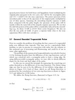
... iy ͪ |ͬ ∞ iy The Fourier transform of h (x ) is now found to be, using P1b, ͫ 1 ␦( y) + iy ͬ 36 Fourier Transforms in Radar and Signal Processing P2b: From P2a and R4, the transform of ͫ 1 ... in the use of the rules -and- pairs method, showing that the method gives a solution for the spectrum quite 39 40 Fourier Transforms in Radar and Signal Processing easily and concisely once a suitable ... units of 1/T, where T is 46 Fourier Transforms in Radar and Signal Processing Figure 3.8 Asymmetric trapezoidal pulse spectra: (a) edges 0.2T and 0.3T ; and (b) edges 0.6T and 0.8T Pulse Spectra...
Ngày tải lên: 18/06/2014, 10:05
Fourier Transforms in Radar And Signal Processing_4 ppt
... k integral The lower edge of the band is then at (k − 1)W The spectrum can now be 70 Fourier Transforms in Radar and Signal Processing Figure 4.3 Narrowband spectrum repeated at intervals 2W ... 4.3 and 4.4 below (wideband and uniform sampling), we simply repeat the spectrum of u In Section 4.5 (Hilbert ˆ sampling), we also include the spectrum of u , the Hilbert transform of u and ... clutter 62 Fourier Transforms in Radar and Signal Processing Figure 3.21 Spectrum of pulse Doppler radar waveform (Figure 3.21 is diagrammatic; the filter bank may be at baseband or a low IF, and may...
Ngày tải lên: 18/06/2014, 10:05
Fourier Transforms in Radar And Signal Processing_5 doc
... signal processing is a digital form of the analytic signal a (t ) exp i (t ) This is what is given by Hilbert sampling and quadrature sampling, discussed 82 Fourier Transforms in Radar and Signal ... itself (Figure 5.2) The (inverse) Fourier transform of this (from P3a, R5, R7a, and R8b) is Figure 5.2 Equivalent forms of U ( f ) 92 Fourier Transforms in Radar and Signal Processing u (t ) = F ... odd and i n for k even However, sampling with a finite window width on a high IF may require 84 Fourier Transforms in Radar and Signal Processing care, as discussed in the next section, and keeping...
Ngày tải lên: 18/06/2014, 10:05
Fourier Transforms in Radar And Signal Processing_6 ppt
... rectangular spectrum, and (b) raised cosine spectrum 116 Fourier Transforms in Radar and Signal Processing Figure 5.18 Mismatch power for rectangular spectrum waveform is greatly oversampled and the ... 5.12 Filter weights with oversampling and trapezoidal rounded gate 103 104 Fourier Transforms in Radar and Signal Processing Figure 5.13 Raised cosine rounding and ͭ ͫ g (t ) = qF sinc qFt sinc ( ... = √2 ͩ ͪ 2 r− 2 (5.18) 100 Fourier Transforms in Radar and Signal Processing Comparing this with (5.5), we see that the weight values now fall very much faster, and this is illustrated in Figure...
Ngày tải lên: 18/06/2014, 10:05
Fourier Transforms in Radar And Signal Processing_7 docx
... U | 2, the power spectrum of the signal, and G, the complex channel response, and then we perform the Fourier transforms defined in (6.6) and (6.7) to give the components of a and B, followed ... signal power, and hence the effect of mismatch would be the most serious If no weighting is required (for example, if the signal spectrum is totally unknown and uniform emphasis across the band ... Fourier transforms If (t ) and G ( f )* | U ( f ) | are a Fourier pair and so are (t ) and | G ( f ) | | U ( f ) | 2, then from (6.6) and (6.7) we have a r = (rT ) and b rs = [(r − s )T ]...
Ngày tải lên: 18/06/2014, 10:05
Fourier Transforms in Radar And Signal Processing_8 pdf
... 142 Fourier Transforms in Radar and Signal Processing Figure 6.8 Sum beam frequency response; effect of bandwidth: (a) 10% bandwidth; and (b) 200% bandwidth Equalization 143 equalization, and ... fractional signal bandwidth (the ratio of the bandwidth to the center frequency), and bandwidths up to 200% (from zero to twice the carrier frequency) can be handled, though of course wider signal bandwidths ... in determining the components of the matrix and vector used to obtain the weights The Fourier transform is 161 162 Fourier Transforms in Radar and Signal Processing also useful for general results...
Ngày tải lên: 18/06/2014, 10:05