connection to the potential equalization system

mcmillan, a. (1998). electrical installations in hazardous areas
... of the flames of the lamps used by miners and the workings were then cleared A torch was inserted into the f methane air cloud, igniting it and burning o f the methane The technique fell into ... than the Standards, then the approved bodies will have to revert to the expert interpretation of more general requirements much as they did before the advent of the more detailed Standards The ... more importantly, to influence the design of any plant or facility to minimize such risks To this end, it is a tool to be used together with the operational requirements in the design of any...
Ngày tải lên: 18/04/2014, 11:03

iec 60092-375 ship board telecommunication cables and radio-frequency cables - general instrumentation, control and communication cables
... insulation from the conductor easily and without damage to the insulation or to the conductor Compliance shall be checked by measuring the force necessary to start the sliding of the insulation in accordance ... material Total number of pairs The total number of pairs shall be: for pairs: 1,2*, 4, 7, 10, 14, 19, 24, 30,37 and 48; - for triples: - All pairs assembled together form the core assembly of the ... If the insulating material is polyvinylchloride compound V75, then the sheath shall consist of polyvinyl chloride compound SV2 A separator between the screening braid and the sheath, when the...
Ngày tải lên: 25/12/2013, 10:44

dye, n. (2000). radio frequency transistors - principles and practical applicat
... proximity to the die The purpose of these matching networks is to not only raise the impedance of the transistor as seen at the edge of the package, but also to transform the impedance values to reduce ... high enough cutoff frequency, f,3 to provide the desired gain at the frequency of operation If the application is switching, then the higher the cutoff frequency, generally the faster the switching ... used in the assembly of the modules Another factor is the epoxy seal used to attach the cover to the flange It is a material similar to that used in attaching caps for discrete transistors and,...
Ngày tải lên: 18/04/2014, 12:26

Advanced Radio Frequency Identification Design and Applications Part 1 ppt
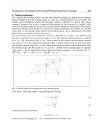
... RFID Systems The total power captured is then |Vin |2 4R tant according to Equation Half of the power is delivered |V |2 to the load which is the maximum available power PA = 8Rin The other ... the reader Section summarises the existing work in the literature on analysing the operating range of UHF RFID systems The existing work is based on either theoretical analysis according to the ... co-ordinate system with its origin at the midpoint at the interval AB, and the reference z axis for the polar angle θ in the direction from A to B (other satisfactory co-ordinate systems could...
Ngày tải lên: 19/06/2014, 23:20

Advanced Radio Frequency Identification Design and Applications Part 2 potx
... assigned to backscatter to the reader for it to decode under a particular modulation mode either ASK or PSK The optimisation of the two states of θ depending on the modulation modes to achieve the ... (i) The selection of the parameter θ, the magnitude squared of which establishes the fraction of the available tag antenna power that is not delivered to the tag chip is one of the keys to lengthening ... If the ideal impedance match is obtained which means the chip input impedance is the complex conjugate of the antenna impedance, half of the captured power is delivered to the chip, the other...
Ngày tải lên: 19/06/2014, 23:20

Advanced Radio Frequency Identification Design and Applications Part 3 pptx
... RFID Tags 31 The received power by the reader is proportional to the (1/d)4 and the gain of the reader and tag antennas In other words, the Read Range of RFID system is proportional to the fourth ... initiator as shown in Fig The initiator is partitioned into three equal parts, and the segment at the middle is replaced with two others of the same length to form an equilateral triangle This is the ... maximum power at the chip from the reader’s antenna and to allow the RFID antenna to send out the strongest signal 3.1 Receiving mode The passive tag in receiving mode is shown in Fig The RFID tag...
Ngày tải lên: 19/06/2014, 23:20

Advanced Radio Frequency Identification Design and Applications Part 4 pot
... covers topics including the system surveying and the working basics of the RFID, especially the physical air interface between the RFID tags (the mobile part) and the so-called Interrogators, ... they increase the system efficiency More coverage area can be achieved with these higher gain antennas, as well as lower power requirements of the Interrogators Most of the necessary theory topics ... related to the central plane, only half the antenna is analyzed and the results are further corrected in order to represent the whole antenna With the dimensions described in Table (Condition 1), the...
Ngày tải lên: 19/06/2014, 23:20

Advanced Radio Frequency Identification Design and Applications Part 5 pptx
... attached to the locus indicates the direction of increasing ω from 860 to 960 MHz Then, tuning the length, as g=0.45 mm, Lf = 5.8 mm and Lt = 6.3 mm, the antenna impedance locus Za (ω) is obtained The ... antenna collects all the transmitted waves, and the pressure levels are indicated on the receiver unit To apply this system to trucks and buses, it is necessary to replace the small-loop antenna ... We also compare the theoretical values of the antenna quality factor (Q) with the experimental results We then consider an important design equation that can be used to determine the self-resonant...
Ngày tải lên: 19/06/2014, 23:20

Advanced Radio Frequency Identification Design and Applications Part 6 potx
... Applications 3.2.6 Q factor The Q factor is important for estimating the antenna bandwidth The radiation Q factor (QR) for electrically small antennas is defined as QR = stored energy (Esto)/radiating ... 3.1, and the Eφ component corresponds to the radiation from the magnetic current source shown in Fig 3.1 There is a 90° phase difference between the Eθ and Eφ components Therefore, the radiated ... (3.19) The requested γ value is determined by taking into account the feeder line impedance Then, Eq (4.17) is used to determine the tap structure The γ0 value is determined by substituting the...
Ngày tải lên: 19/06/2014, 23:20

Advanced Radio Frequency Identification Design and Applications Part 7 pdf
... antenna and the IC uses its power harvesting circuit to provide power to the digital portion of the circuit The power is then used by the IC to communicate with the reader The RFID system can ... Gt is the gain of the antenna on the reader, Gr is the gain of the antenna on the tag, λ is the free-space wavelength of the transmitting frequency by the reader, R is the distance between the ... of mm The IC is inserted into the tap arm The antenna and IC are placed on a piece of polystyrene foam attached to the metal plate The thickness of the foam is 1.5 mm, and the size of the square...
Ngày tải lên: 19/06/2014, 23:20

Advanced Radio Frequency Identification Design and Applications Part 9 pot
... to the other material while others will take them As the material is separated, the transferred electrons may or may not move back to the original material depending on, among other things, the ... conductor As an example, a negatively charged insulator will cause the side nearest the insulator to develop a positive charge resulting in a negative charge on the opposite side of the conductor The ... Electronics are generally classified into groups based on their tolerance to charge potentials The class is determined by the model used to test the equipment The models each have a different discharge...
Ngày tải lên: 19/06/2014, 23:20

Advanced Radio Frequency Identification Design and Applications Part 10 pdf
... is restricted to the RFID tag search system Therefore, to design secure protocols in the RFID tag search system, we need to identify threats which are restricted to the search system We will ... each other If Protocol uses the technique in Protocol 2, Protocol can become secure against intercept attacks Another drawback of the protocol is a storage cost In the protocol, tags should store ... to the broadcasted identifier ID j (5) If the reader receives the reply from the tag Tj , the reader R can know the existence of the tag Tj Despite the simplified structure for a tag search the...
Ngày tải lên: 19/06/2014, 23:20

Advanced Radio Frequency Identification Design and Applications Part 11 docx
... the criteria to classify the tag placement by the density of tags and the regularities of tag positions Several researchers managed their works to apply the concept to their application and to ... cost to 15 U.S cents and the EPCglobal tries to reduce the price of tags to cents(RFID journal, nd) After the installation of RFID tags, the efforts to maintain the landmarks are barely needed These ... estimate the current position and the heading angle The cost of the INS systems was very high and the size was large for the indoor mobile robots, until the advances of the micro-electromechanical systems...
Ngày tải lên: 19/06/2014, 23:20
Advanced Radio Frequency Identification Design and Applications Part 12 ppt
... of the magnetic field’s behavior is essential in understanding the overall system designs required to transmit energy from the above-ground interrogator to the tag and from the tag back to the ... is useful to define it as proportional to the ratio of the inductance to the resistance of the tag’s receiving coil It can also be defined as the ratio of the resonance frequency to the bandwidth, ... Here the coil is centered directly over the munition and the ground is not shown The other figures show the geometry (top-left and bottom-right) and mesh (top-right) for the munition model The...
Ngày tải lên: 19/06/2014, 23:20

Advanced Radio Frequency Identification Design and Applications Part 13 docx
... correspond to the transmitting coil moving parallel to the axis of the munition The right curves correspond to the coil moving perpendicular to its axis For a given munition depth, the strength of the ... required to receive the signal The permeable filler placed in a groove to help increase input signal to the tag has little effect on tag output As in the case of the signal to the RFID tag, the tag’s ... shows the magnetic vector equipotential lines from both tag types, in air and in a groove on the munition The magnetic field is parallel to these lines and larger when the lines are closer together...
Ngày tải lên: 19/06/2014, 23:20

Advanced Radio Frequency Identification Design and Applications Part 14 ppt
... minimal weight in the graph To apply the LOP to the MWHP, it is necessary to convert the LOP into a minimization problem because the LOP is a maximization problem for finding the order of having ... 5-(a) To apply the WMHP to the LOP, weights of edges are assigned to w΄, the weight of an edge assigned to one minus LID proximity value It means that the lower the weight of an edge is, the higher ... time To consider the closeness value for an observation query and a trajectory query altogether, the function calculates the sum of LIDProx_OQ(i, j) and LIDProx_TQ(i, j) with the weight value The...
Ngày tải lên: 19/06/2014, 23:20

Advanced Radio Frequency Identification Design and Applications Part 15 pdf
... simulator hardware design The general structure of the tag simulator is shown in Fig 1, the whole system is divided into two major parts, the RF board PCB2 and the baseband board PCB1 The PCB2 ... Transmitting FIFO and the channel assignment principle In the DSP commands, each tag needs to write the replied data into the FIFO, and the width of the data is 32bit, the width of the replied data ... connected to the FPGA, to configure the DAC’s controlling memory 2.1.4 User’s interface module The user’s interface module is composed of keys and LED, the keys are input tools for users to choose the...
Ngày tải lên: 19/06/2014, 23:20

Radio Frequency Identification Fundamentals and Applications, Bringing Research to Practice Part 1 potx
... data storage in RFID systems and their impact on the quality factors of the resulting system In the final chapter of this book the authors introduce the widely applied RFID middlewares with the ... Bringing Research to Practice Contact-less inductively coupled systems are used to identify objects in the range of the lowest frequencies (in the wave ranges from medium to short) These systems are ... process, it is necessary to define a maximum working distance of the RFID system This parameter determines the distance between the specified point of the RWD’s and the midpoint of the tag’s antenna...
Ngày tải lên: 21/06/2014, 11:20

Radio Frequency Identification Fundamentals and Applications, Bringing Research to Practice Part 2 potx
... Research to Practice For the sake of the fact that the shape of RWD loop determines the magnetic field, there has been presented below the method of calculating the magnetic induction B created on the ... environment If the rectangular contour abcd (Fig 14-b) will be assumed on the boundary of the ferromagnetic object then the fallowing equation is fulfilled in the open circuit for the vector of magnetic ... vector potential A when determining induction B in the tag placement area The dependences (40) and (42) show that there is continuity of vector potential at the boundary in the Fig 14 where the...
Ngày tải lên: 21/06/2014, 11:20

Radio Frequency Identification Fundamentals and Applications, Bringing Research to Practice Part 3 pdf
... Finally, let eij denote to the j-th component of the Ei state vector The goal is to describe the transition probability matrix P for the model, from every state i to another state j The stationary state ... arbitrary cycle, the evolution of the system to the next cycle only depends on the current state Thus, a DTMC can be used to study the behavior of the RFID system Next section describes this ... unidentified tags in the j-th cycle The following figures illustrate the model They describe the state of the system for two consecutive cycles, showing tags entering and leaving the system, in both...
Ngày tải lên: 21/06/2014, 11:20