chc 4 cross flow combustor heat exchanger for hydrogen oxidation

Báo cáo hóa học: " Performance evaluation on an air-cooled heat exchanger for alumina nanofluid under laminar flow" pdf
... nanofluid with a high heat convective performance for heat exchange can help reduce the volume of the heat exchanger In addition, using nanofluid with higher heat transfer performance instead of ... sinks, plate heat exchangers, double-tube heat exchangers, or heated enclosures, and seldom used in air-cooled heat exchangers Since the ultimate goal of radiators is to discharge heat into the ... temperature controller (TTM-J4, TOHO, Japan) with SSR (SSR -40 DA, Manax, Taiwan) and heater (300 W), the nanofluid was pumped to an air-cooled heat exchanger for circulation The heat exchange capacity...
Ngày tải lên: 21/06/2014, 01:20
THIẾT KẾ HỆ THỐNG SẤY DẦU FO DÙNG CHO LÒ HƠI BẰNG THIẾT BỊ TRAO ĐỔI NHIỆT ỐNG LỒNG ỐNG SỬ DỤNG NĂNG LƯỢNG MẶT TRỜI DESIGNING A SYSTEM FOR DRYING BOILER FUEL OIL WITH A DOUBLE TUBE HEAT EXCHANGER DEVICE USING SOLAR ENGERGY pptx
... 0,3 0 ,4 0,5 0,6 0,7 NHIỆT ĐỘ ĐƠNG ĐẶC: 200C 0,8 0,9 70 9,7 19,3 29,0 38,7 48 ,3 57,9 67,7 77,3 86,9 96,5 193 290 387 48 3 80 8,5 16,9 25 ,4 33,8 42 ,3 50,7 59,2 67,6 76,1 84, 6 169 2 54 338 42 3 90 ... t2’’ – t’2) Q 225 ,43 5.3600 ' t 1'' = t1 − = 80 − = 44 , [ C] G1.C p1 5 ,4. 4,1 74. 1000 Q = G2.Cp2 ( t2’’ – t’2) = Từ nhiệt độ trung bình t1 nước nóng: t1 = 0, (t’1 + t’’1) = 0, (80 +44 ) = 62 [0C] Với ... bảng ta xác định được: Cpl = 4, 1 74 [kJ/kg.K] ρ1 = 982,04kg / m ; γ = 0 ,46 54. 10 −6 m / s; λ1 = 0,6605 W / m.K ; Pr f = 2,8 94 Với nhiệt độ trung bình dầu lạnh t2 = 47 ,5 [0C], sử dụng bảng, tốn...
Ngày tải lên: 29/06/2014, 16:20

apress pro.dynamic..net.4.0.applications.data-driven.programming.for.the..net.framework
... Floor, New York, NY 10013 Phone 1-800-SPRINGER, fax 201- 348 -45 05, e-mail ordersny@springer-sbm.com, or visit http://www.springeronline.com For information on translations, please e-mail info@apress.com, ... of ED books may be purchased in bulk for academic, corporate, or promotional use eBook versions and licenses are also available for most titles For more information, reference our Special Bulk ... Referencing Controls on Forms 68 Adding References 70 Testing 75 Summary 75 ■Chapter 4: D ynamic WinForms 77 Instantiating Forms ...
Ngày tải lên: 06/08/2013, 17:29

Formation of Aerobic Granular Sludge in a Continuous-Flow Reactor – Control Strategy for the Selection of Well-Settling Granular Sludge
... mode (Run 2) was changed from 230 to 341 mg/L on day 22 to increase the NH4-N loading rate Iron in the form of FeSO47H2O and phosphorus in the form of KH2PO4 were added to the influent as a trace ... the formation of aerobic granular sludge - 255 - 0.10 100 80 60 40 20 0 + NH4+-N removal efficiency [%] 0.20 NH4 -N removal rate [kg-N/m3/day] HRT [day] + NH4 -N removal rate [kg-N/m3/day] NH4+-N ... 58(2), 44 5 45 0 Li A J and Li X Y (2009) Selective sludge discharge as the determining factor in SBR aerobic granulation: Numerical modelling and experimental verification, Water Res., 43 ( 14) , 3387-3396...
Ngày tải lên: 05/09/2013, 10:15
Simulation of the thermal borehole resistance in groundwater filled borehole heat exchanger using CFD technique
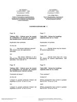
... 273. 94 283.79 293.63 298.65 289.25 286.60 M1 / M7 M2 / M8 M3 / M9 M4 / M10 M5 / M11 M6 / M12 59 .49 55.05 49 . 54 46. 74 24. 68 39 .40 Received q' [W·m-1] Results for the U-pipe model (Mu) Both total heat ... Issue 3, 2010, pp.399 -41 0 40 3 Table Boundary conditions for simulations M1-M12 for U-pipe model (Mu) and received heat flow per metre of borehole using total heat transfer flow (THT) Boundary conditions: ... the model for the different boundary conditions, heat flows Total heat transfer (THT) Conductive heat transfer (CHT) req [m] cTpw 0. 04 0.0355 req [m] cq"pw 0. 04 0.0283 Figure shows a flow chart...
Ngày tải lên: 05/09/2013, 14:58

Effect of periodic suction on three dimensional flow and heat transfer past a vertical porous plate embedded in a porous medium
... 0.003889 0.003723 0.2 0.186269 0.18 144 1 0.180830 0.180797 0.5 0 .46 549 6 0 .46 1281 0 .46 0627 0 .45 7991 2.0 2.15 840 0 2. 145 131 2.12 049 7 2.0 248 07 5.0 9.873 545 9.3 549 39 9.287622 9.280233 Conclusion From ... -6 .46 04 21.806 -6 .46 48 4. 4 Rate of heat transfer The rate of heat transfer at the wall i.e the heat flux in terms of Nusselt number Nu for different values of α and Kp are entered in Table The heat ... u11 ′ ′ ′ θ11 (44 ) The corresponding boundary conditions are u11 = 0, θ 11 = at y = 0, u11=0, θ 11 = as y→ ∞ (45 ) (43 ) Solving equations (43 ) and (44 ) under boundary condition (45 ) and using equations...
Ngày tải lên: 05/09/2013, 14:58
A VIETNAMESE ENGLISH CROSS CULTURAL STUDY ON GESTURES FOR GREETING
... 48 .1 69.6 42 .4 17.6 22.2 43 .5 24. 2 5.9 7 .4 26.1 Waving 9.1 7 .4 4.3 15.2 11.8 7 .4 21.7 42 .4 47.0 55.6 34. 8 36 .4 35.3 37.0 39.1 36 .4 29 .4 29.6 43 .4 High-5 0 0 3.0 0 4. 3 9.1 7 .4 4.3 6.1 3.7 4. 3 3.03 ... 22.2 4. 3 17 .4 (%) (%) (%) 32.0 24. 0 16.0 0 28.0 40 .0 22.0 4. 0 12.0 32.0 26.0 42 .0 24. 0 20.0 44 .0 8.0 10.0 20.0 72.0 80.0 44 .0 back/shoulder Bowing Wai Raising 4. 0 10.0 12.0 (50) 0 2.0 4. 0 4. 0 ... 52.2 42 .4 41.2 41 .2 43 .4 45.5 29 .4 29 .4 34. 8 12.1 Hand shaking Female (%) 11.8 11.8 8.7 03 0 11.8 21.7 12.1 0 17.6 34. 8 2.1 0 4. 3 Waving High-5 Hugging 21.2 Patting on shoulder/ back 39 .4 11.8...
Ngày tải lên: 07/09/2013, 13:58

An Introduction to Intelligent and Autonomous Control-Chapter 4:Design of Structure-Based Hierarchies for Distributed Intelligent Control
Ngày tải lên: 17/10/2013, 19:15
iec 60269-4 low-voltage fuses - supplementary requirements for fuse-links for the protection of s
... Licensee=/5 943 408001, 03/29/20 04 21:23 :49 MST Questions or comments about this message: please call the Document Policy Group at 303-397-2295 I M 48 448 93 ù L b bb4 M - 3- 269 -4 Amend O IEC:1995 FOREWORD ... Licensee=/5 943 408001, 03/29/20 04 21:23 :49 MST Questions or comments about this message: please call the Document Policy Group at 303-397-2295 ~~ ~ Y ~~~ / - IEC 269 PT *4 b W 48 448 91 00238 24 W Publication ... articles, paragraphes et tableaux I E C 2b4 P T * 269 -4 O I E C 1986 86 48 448 73 O0238 34 -9- LOW-VOLTAGE FUSES Part 4: Supplementary requirements for fuse-links for the protection of semiconductor devices...
Ngày tải lên: 25/12/2013, 10:55
Báo cáo khoa học: Anti-arthritis effects of vitamin K2 (menaquinone-4) ) a new potential therapeutic strategy for rheumatoid arthritis doc
... cartilage destruction in rats with collagen induced arthritis Ann Rheum Dis 64, 49 4 49 6 FEBS Journal 2 74 (2007) 45 88 45 94 ª 2007 The Authors Journal compilation ª 2007 FEBS ... Therefore, vitamin K2 FEBS Journal 2 74 (2007) 45 88 45 94 ª 2007 The Authors Journal compilation ª 2007 FEBS 45 91 Anti-arthritis effects of vitamin K2 H Okamoto et al may represent a new strategy for ... Imaging 4, 1–6 23 Nakazawa F, Matsuno H, Yudoh K, Katayama R, Sawai T, Uzuki M & Kimura T (2001) Methotrexate FEBS Journal 2 74 (2007) 45 88 45 94 ª 2007 The Authors Journal compilation ª 2007 FEBS 45 93...
Ngày tải lên: 30/03/2014, 03:20
Báo cáo khóa học: UDP-galactose 4-epimerase from Kluyveromyces fragilis Evidence for independent mutarotation site pdf
... presence of an essential arginine 35 36 37 38 39 40 41 42 43 44 45 residue at the substrate-binding site of the enzyme J Biol Chem 261, 45 19 45 24 Beebe, J.A & Frey, P.A (1998) Galactose mutarotase: ... Enzymol 41 , 47 1 48 4 11 Fishman, P.H., Pentchev, P.G & Bailey, J.M (1975) Mutarotase from higher plants Methods Enzymol 41 , 48 4 48 7 12 Smits, P.H.M., deHaan, M., Maat, G & Grivell, L.A (19 94) The ... the genes for aldose 1-epimerase (mutarotase) and UDP-glucose 4- epimerase J Bacteriol 172, 40 37 40 47 14 Majumdar, S (2000) Studies on assembly pathway and active site of UDP-glucose 4- epimerase...
Ngày tải lên: 30/03/2014, 13:20

fundamentals of heat exchanger design
... 244 4. 2.1 4. 2.2 4. 2.3 248 249 251 4. 2 4. 3 Temperature Effect Length Effect Combined Effect 236 236 239 239 239 239 258 4. 3.1 4. 3.2 4. 3.3 4. 3 .4 4 .4 Additional Considerations for Extended Surface Exchangers ... Properties 41 9 42 0 42 0 42 2 Surface Basic Heat Transfer and Flow Friction Characteristics 42 5 7.1 Basic Concepts 42 6 7.1.1 7.1.2 7.1.3 7.1 .4 426 42 9 43 8 43 9 7.2 Boundary Layers Types of Flows Free and Forced ... Counterflow Exchanger 4. 1.3 Single-Pass Parallelflow Exchanger 4. 1 .4 Single-Pass Unmixed–Unmixed Cross ow Exchanger 4. 1.5 Other Single-Pass Exchangers 4. 1.6 Multipass Exchangers 232 Nonuniform Overall Heat...
Ngày tải lên: 02/04/2014, 15:24
heat exchanger design handbook (1st issue), by e u schlunder
... Regenerators, 4. 1.3 4. 1 .4 4.1.5 4. 1.6 4. 1.7 4. 1.8 Shells, C Ruiz Tube Plates, C Ruiz Tubes, C Ruiz Expansion Joints, C Ruiz 4. 2 SHELL-AND-TUBE HEAT EXCHANGERS: ELEMENTS OF CONSTRUCTION 4. 2.1 4. 2.2 Introduction, ... no-phase-change heat exchanger performance Pressure drop and pumping power J The choice of formulation r MD4 L A 1983 Hemisphere Publishing Corporation 1.2 .4- l 1.2 .4- l 1.2 .4- I 1.2 .4- l 1.2 .4- 2 1.2 .4- 2 1.2 .4- 3 ... Introduction, C Ruiz Methods of Analysis, C Ruiz M Morris 4. 4.2 4. 4.3 4. 4 .4 4.5 MATERIALS OF CONSTRUCTION AND CORROSION 4. 5.1 4. 5.2 4. 5.3 Introduction, J F Lancaster Materials of Construction,...
Ngày tải lên: 02/04/2014, 15:25

báo cáo hóa học: " Simulator sickness when performing gaze shifts within a wide field of view optic flow environment: preliminary evidence for using virtual reality in vestibular rehabilitation" pptx
... SSQ:Disorientation SSQ:Total 17 24 28 30 26 30 32 34 13 13 15 15 15 17 11 15 24 28 31 35 39 38 40 11 6 8 11 15 31 30 33 37 41 40 40 25 15.0 06 12 5.2 73 29 16.0 04 8.0 43 31 16.2 04 simulators and head ... http://www.jneuroengrehab.com/content/1/1/ 14 Figure Experimental set-up for Task H, Visit (see Tables and for explanation) Experimental set-up for Task H, Visit (see Tables and for explanation) Subjects stood upright on force platform ... Pract 1998, 48 (42 9):1131-1135 Page of 10 (page number not for citation purposes) Journal of NeuroEngineering and Rehabilitation 20 04, 1: 14 10 11 12 13 14 15 16 17 18 19 20 21 22 23 24 Whitney SL,...
Ngày tải lên: 19/06/2014, 10:20
Báo cáo hóa học: " A cross-layer resource allocation scheme for spatial multiplexing-based MIMO-OFDMA systems" docx
... 625–6 34 (2005) 15 G Song, Y Li, Cross- layer optimization for OFDM wireless networks-Part I: theoretical framework IEEE Trans Wirel Commun 4, 6 14 6 24 (2005) 16 X Qiu, K Chawla, On the performance ... of 144 kbps For best-effort users, there are no rate requirements However, we assume a threshold rate of 512 kbps for the minimum user satisfaction Furthermore, we set U0 = and Umax = 10 for ... allocation for OFDM systems IEEE Trans Wirel Commun 8, 288–296 (2009) 14 G Song, Y Li, Cross- layer optimization for OFDM wireless networks-Part II: algorithm development IEEE Trans Wirel Commun 4, 625–634...
Ngày tải lên: 21/06/2014, 01:20

báo cáo hóa học:" Research Article Variable Viscosity on Magnetohydrodynamic Fluid Flow and Heat Transfer over an Unsteady Stretching Surface with Hall Effect" pot
... 1 .43 86 64 1.3 940 31 1.3 744 22 1.3 644 11 1.358689 3rd ord 1.711172 1.5 549 02 1 .43 8677 1.3 940 40 1.3 744 29 1.3 644 17 1.358695 4th ord 1.711172 1.5 549 02 1 .43 8677 1.3 940 40 1.3 744 29 1.3 644 17 1.358695 m bvp4c ... 1.5 549 02 1.6 547 80 1.759550 1.869358 1.9 843 56 2.1 047 02 4th ord 1.5 549 02 1.6 547 80 1.759550 1.869358 1.9 843 56 2.1 047 02 β2 0.1 0.2 0.3 0 .4 0.5 0.6 2nd ord 1.5 548 80 1.5 541 40 1.55 346 4 1.552 845 1.5522 74 ... 1. 346 977 1.5 549 02 2.0 947 28 2.780758 3.5 249 63 4. 296187 5.081855 4th ord 1. 346 977 1.5 549 02 2.0 947 28 2.780758 3.5 249 63 4. 296187 5.081855 m 0.1 1.0 2.0 3.0 4. 0 5.0 6.0 2nd ord 1.711 146 1.5 548 80 1 .43 8664...
Ngày tải lên: 21/06/2014, 11:20
Báo cáo hóa học: " Research Article Cross Layer PHY-MAC Protocol for Wireless Static and Mobile Ad Hoc Networks" pot
... 18 Total packets received 2800 240 0 2000 1600 1200 800 15 12 40 0 35 40 45 50 20 25 30 Time (s) 35 40 45 50 PSc basic STD 310 Gain over DCF 802.11 (%) 255 200 145 90 35 −20 Packets RCVD 6.1.1 ... 1500 m Random DSSS, IEEE 802.11a 24. 05 homo/hetero-geneous variable = 0.5– ., 5, 20 0.281838 W 0.0072 14 W 250 100 meters 45 % of PtMAX 30% of PtMAX 10 CBR/UDP 2 048 100–8192 15–1023 25–50, 50 (default) ... DCF specifies that a node needs to sense the medium before transmitting If the medium is idle, the node waits for a random deferral time before transmitting This back-off time is a random value...
Ngày tải lên: 21/06/2014, 22:20

Báo cáo hóa học: " Research Article Cross-Layer Admission Control Policy for CDMA Beamforming Systems" docx
... set to 10 4 , while different target Table 6: Simulation parameters B g R1 λ1 μ1 Ψ1 D1 M η1 3. 84 MHz 3 .49 98 144 kbps 0.25 0.1 2.25 0.5 a γ0 R2 λ2 μ2 Ψ2 D2 η0 η2 90.25 14 1.0 942 dB 3 84 kbps 0.5 ... 0.07 14 0.0359 0.0537 [0, 3] 0.07 64 0.0280 0.0522 [1, 2] 0. 043 4 0. 041 2 0. 042 3 [3, 2] 0.0179 0.0379 0.0279 CS: Pb 0.0978 0.1185 0.0505 0.0210 CS: Pb 0.0390 0.0171 0. 040 0.0569 CS: Pb 0.06 84 0.0678 ... Calderbank, “Space-time codes for high data rate wireless communication: performance criterion and code construction,” IEEE Transactions on Information Theory, vol 44 , no 2, pp 744 –765, 1998 G J Foschini,...
Ngày tải lên: 22/06/2014, 19:20