attempting to compare objects using the relational operators

McGraw.Hill PIC Robotics A Beginners Guide to Robotics Projects Using the PIC Micro eBook-LiB Part 1 pdf
... Building a Walter Tortoise Drive and Steering Motors Modifying the HS425BB Servomotor Sheet Metal Fabrication Shell Finding the Center of Gravity Attaching Bumper to Robot Base Bumper Switch Mounting the Steering Servomotor ... The programming carrier board (see Fig. 1.3) has a socket for inserting the PIC chip and connecting it to the computer, via the printer port, for program ming. The programming board connects to the computer’s printer port via a DB25 cable. If the computer only has one printer port with a printer connect ... Basic Servomotor Bracket Assembly Assembling MultipleServomotor Assemblies Building a FiveServomotor Robotic Arm Servomotors Servomotor Controllers Simple Servomotor Controller Four and FiveServomotor Controllers...
Ngày tải lên: 10/08/2014, 04:22

McGraw.Hill PIC Robotics A Beginners Guide to Robotics Projects Using the PIC Micro eBook-LiB Part 2 pot
... deep (levels) one has moved into subdirectories The root directory is the top of the directory hierarchy From the Windows subdirectory type in cd\ and hit the Enter key to move to the root directory of the hard drive ... An alternate to pasting the selected files is to select all the files as before, copy the files, drag the selected files to the PBC directory using the mouse, and then release the mouse button (see Fig ... The file will load and numbers will be displayed in the code window on the left Insert the 16F84 into the socket on the programming board, and select the Program option from the Run menu. An alternative to using the menu option is to press the ...
Ngày tải lên: 10/08/2014, 04:22

McGraw.Hill PIC Robotics A Beginners Guide to Robotics Projects Using the PIC Micro eBook-LiB Part 3 pps
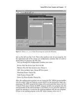
... have the option of either trou bleshooting the problem or using the EPIC DOS program For instructions on using the EPIC software, DOS version, see Chap The schematic of the circuit needed to test the PICmicro is given in Chap ... Programming the PIC Chip To program the PIC chip, we must connect the EPIC programming carrier board (see Fig 5.8), to the computer The EPIC board connects to the printer port The printer port is also called the parallel port ... compiles the program, and then ends the DOS session To compile the program using CodeDesigner, either select compile under the Compile menu or hit F5 CodeDesigner automatically starts the PicBasic Pro...
Ngày tải lên: 10/08/2014, 04:22

McGraw.Hill PIC Robotics A Beginners Guide to Robotics Projects Using the PIC Micro eBook-LiB Part 4 ppt
... controller is programmed and ready to run You can verify the program if you like by hitting (or highlighting) the Verify button This initiates a comparison of the program held in memory to the program stored in the ... purchased the components, you can quickly set up the test circuit If not, the components are listed again at the end of this chapter; you will need the com ponents to build the circuit The solderless breadboard ... you can transfer the components onto a standard printedcircuit board and solder it together with the fore knowledge that the circuit functions properly A partial cutaway of the top surface shows some of the internal structure of...
Ngày tải lên: 10/08/2014, 04:22

McGraw.Hill PIC Robotics A Beginners Guide to Robotics Projects Using the PIC Micro eBook-LiB Part 5 docx
... Depending upon which PicBasic compiler is used, the commands are a little different For the PicBasic compiler, the command to write to a register is the poke command The program line to write the decimal value 1 into the TRISB register will look like this: ... Once the port lines have been configured (input or output) using the TRIS reg ister, we can start using it To output a binary number at the port, simply write the number to the port, using the poke (PicBasic) or trisx.x (PicBasic Pro) command The binary equivalent of the decimal number will be outputted, ... poke 134,1 The number after the poke command is the memory address that the com mand will write to, in this case 134 The number 134 is the memory address of the TRISB for port B The next number,...
Ngày tải lên: 10/08/2014, 04:22

McGraw.Hill PIC Robotics A Beginners Guide to Robotics Projects Using the PIC Micro eBook-LiB Part 6 pps
... Keep the servomotor horn attached to the front of the servomotor Once the screws are removed, gently pull off the front cover of the servomotor The output gear will stay attached to the front cover, ... Rear axle bracket detail the ends of the upper bracket Then secure the upper bracket to the bumper using 540 machine screws and nuts Attaching Bumper to Robot Base The bumper is attached to the robot body by the upper bracket ... pulse width of 1 ms sent 50 to 60 times per second (Hz) will cause the servo motor to rotate in one direction A pulse width of 2 ms will cause the servo motor to turn in the opposite direction There are two ways we can stop the servomotor from ...
Ngày tải lên: 10/08/2014, 04:22

McGraw.Hill PIC Robotics A Beginners Guide to Robotics Projects Using the PIC Micro eBook-LiB Part 7 pps
... attach the U bracket to the servomotor so that the drive wheel is pointing forward Walter’s Turtle 109 Figure 8.33 Closeup photograph detailing bump switch Photoresistor The CdS photoresistors (see Fig ... light intensity also vary from one another and then are not as closely matched Once you have a pair of CdS cells to use, they need to be attached to the robot I soldered the CdS cells and capacitors to a small piece of perforated ... Figure 8.38 shows both the front and back of the sen sor array The opposite side of the servomotor bracket that holds the continuous rota tion servomotor is perfect for mounting the photoresistor I used a small piece...
Ngày tải lên: 10/08/2014, 04:22

McGraw.Hill PIC Robotics A Beginners Guide to Robotics Projects Using the PIC Micro eBook-LiB Part 8 ppt
... exposed side of the tape is immediately secured to the gearbox motor bracket Then the motor is positioned on the bottom of the vehicle base, the protective covering of the tape is removed, and the gearbox motor is firmly placed onto ... and the gearbox motor is firmly placed onto the bottom of the vehicle base (see Fig 9.9) The second gearbox motor is secured to the other side in a similar manner Back wheels The shaft diameter of the gearbox motor is a little too small to make a good ... top of the picture has an orange cowl that is covering the gears Notice the flat mounting bracket that is perfect for securing to the vehicle base The double sided tape is cut lengthwise to fit the base of bracket to the gearbox motor The exposed side of the tape is immediately secured to the gearbox motor bracket...
Ngày tải lên: 10/08/2014, 04:22

McGraw.Hill PIC Robotics A Beginners Guide to Robotics Projects Using the PIC Micro eBook-LiB Part 9 pps
... The centered 1/4in hole allows you to remove or attach the ser vomotor screw that holds the servomotor horn (and leg assembly) to the ser vomotor Make sure these three holes line up with the holes on the servomotor horn you intend to use The front legs only need two holes—one for the pivot and the other for the ... unscrewing the center mounting screw from the horn Once the screw is removed, pull the horn off Keep the leg attached to the horn Apply power to the servomotor and connect the control line of the servomotor to ... power to the servomotor and connect the control line of the servomotor to RB4 This will center the servomotor’s rotational position Now reattach the servomotor horn to the servomotor, positioning the leg to be in the center position, as shown in Fig...
Ngày tải lên: 10/08/2014, 04:22

McGraw.Hill PIC Robotics A Beginners Guide to Robotics Projects Using the PIC Micro eBook-LiB Part 10 ppsx
... Press the 2 key, then the # key to train the second word, and so on The circuit will accept up to either 20 or 40 words, depending on the lengths of the words You do not have to enter 20 words into memory to use the circuit ... was trained as word number 5, then saying the word directory into the microphone will cause the number 5 to be displayed Error codes The chip provides the following error codes 55 � word too long 66 � word too short ... resistors R4 and R5 The reference voltage is placed on pin 5 of the comparator Pin 4 of the comparator is connected to the LED lead on the speech recognition circuit Whenever a word is detected, the LED blinks off momentarily...
Ngày tải lên: 10/08/2014, 04:22

McGraw.Hill PIC Robotics A Beginners Guide to Robotics Projects Using the PIC Micro eBook-LiB Part 11 doc
... vomotor to the A portion of the bracket; this will be the wrist servomotor The wrist servomotor motor is attached to the gripper first Remove the servomotor horn from the servomotor, if you ... assemble the base, center the bottom servomotor before attaching the upper A bracket This forms the base of the robotic arm To secure the base to a platform, four holes are drilled in the bottom bracket (see Fig ... al to provide a good base that doesn’t topple when the robotic arm moves and lifts objects The two middle servomotors are assembled onto the base, and the servogrip per is attached to the top, completing the robotic arm (see Figs...
Ngày tải lên: 10/08/2014, 04:22

McGraw.Hill PIC Robotics A Beginners Guide to Robotics Projects Using the PIC Micro eBook-LiB Part 12 pptx
... Attaching a servomotor horn to servomotor base When the top plate is secured to the bearing, the top of the wood dowel should be right underneath the top plate Place the bottom servomotor brack ... et of the robotic arm on top of the top plate Secure the servomotor bracket (and top plate) to the underlying dowel through the four center holes in the top bearing plate (see Fig 12.46) The top section of the robotic arm is fitted to the base servomotor brack ... Figures 12.37 and 12.38 show the sides for the base Figure 12.39 is a metal baseplate The two servomotor blocks are mount ed to the baseplate, using wood screws through the bottom The servomotor is mounted to the wood blocks (see Fig...
Ngày tải lên: 10/08/2014, 04:22

McGraw.Hill PIC Robotics A Beginners Guide to Robotics Projects Using the PIC Micro eBook-LiB Part 13 docx
... remove the goto hold line you wrote in the program Place the goto hold line at the end of the “First movement.” Check position, adjust if necessary, then move the goto hold line to the end of the “Second movement.” ... hole to remove any burrs with a file or deburring tool Assembly When you assemble the servomotors to the servomotor brackets, center each servomotor before attaching the servomotor shaft to the hornbracket assem ... ket material to the bottom of the plastic footpad to make the pad nonskid The footpads provide a larger surface area that makes it easier for the biped to balance and walk They are attached to the bottom U bracket of the...
Ngày tải lên: 10/08/2014, 04:22

McGraw.Hill PIC Robotics A Beginners Guide to Robotics Projects Using the PIC Micro eBook-LiB Part 14 potx
... gram 2 The LED D1 flashes after the auto light adjustment to signal you to put the target in front of the camera The D1 LED also flashes when the robot is in the stop loop I included the flashing LED because it’s not always easy to see the LCD display ... At any time you need or want to reconnect the CMU camera serial interface to a PC, you will need to place the MAX232 chip back onto the board Plug the TTL cable onto the appropriate header pins on the CMU camera ... ter is used to determine range of the object If the object (PIX gets too large) comes too close to the robot, the robot will back away from the object Everything stated about program 2 also applies to this program...
Ngày tải lên: 10/08/2014, 04:22

McGraw.Hill PIC Robotics A Beginners Guide to Robotics Projects Using the PIC Micro eBook-LiB Part 15 pot
... assembly multipleservomotor assemblies, 189–192 finished product (photograph), 222, 223 parts list, 223–224 servomotor brackets, 185–189 servomotor controllers, 199–215 servomotors, 197–199, 215 Robotic arm gripper, ... xcopy, 16 ABOUT THE AUTHOR John Iovine is the author of several popular TAB titles that explore the frontiers of scientific research He has written Homemade Holograms: The Complete Guide to Inexpensive, ... 88–89 parts list, 123–124 photographs of finished product, 122 photoresistor, 109–111 power, 119–120 program, 115–119 schematic, 114–118 sensor array, 112–114 servomotor, 90–97 sheet metal fabrication,...
Ngày tải lên: 10/08/2014, 04:22

Tracking of multiple objects using the PHD filter
... of objects In a tracking scenario, the number of objects can be time-varying, so the tracking algorithm has to detect the change of the number of objects, and automatically track new objects The ... After the updating step in the GMPHD …lter, if two or more components have the same label, then this label is given to the one with the largest weight and new labels are assigned to the other ... of objects and activity recognition There are methods to obtain the object identities for the PHD …lter Firstly, some methods use the particle PHD …lter for pre-…ltering the data input to other...
Ngày tải lên: 11/09/2015, 16:08

Tài liệu Using the Data Form Wizard to Create a Windows Form phần 1 pdf
... or views you want to use in your form The area on the bottom left of the dialog box shows the tables and views you can access using your form The area on the bottom right shows the tables and views ... between the rows in the Customers table with the rows in the Orders table: When you move to a new row in the Customers table, the rows from the Orders table will be displayed in your form Set the ... To add the relationship to your form, click the right-arrow button If you don't this, your relationship won't be added to your form Click the Next button to continue Select the columns from the...
Ngày tải lên: 24/12/2013, 01:17

Tài liệu Using the Data Form Wizard to Create a Windows Form phần 2 doc
... current row Add The Add button allows you to add a new row Delete The Delete button allows you to delete the current row Cancel The Cancel button allows you to cancel a change made to the current ... where the CustomerID is ALFKI; the bottom part of the form contains a DataGrid control that displays the rows from the Orders table for that customer When you move to the next row in the Customers ... table, the rows from the Orders table for that customer are automatically displayed in the DataGrid Feel free to try out the other buttons on your form to add, modify, and delete rows in the Customers...
Ngày tải lên: 24/12/2013, 01:17

Tài liệu Using the Get* Methods to Read Column Values doc
... C# type You use this table to figure out which method to call to get a specific column type For example, if you need to get the value of a bigint column, you call the GetInt64() method that returns ... between and 216 - (65,535) Note The standard C# types are defined in the System namespace Table 9.4 shows the SQL Server types, the compatible standard C# types, and the DataReader Get* methods that ... Note You can see the SQL Server types and the values supported by those types in Table 2.3 of Chapter 2, "Introduction to Databases." Note The Get* methods are defined in all of the DataReader...
Ngày tải lên: 24/12/2013, 01:17
