and graphene based devices circuits and sensors for vlsi design
Charge and spin transport in graphene based devices
... affect the graphene mobility Our results raise the importance of ideal choice of material for graphene- based heterostructure devices before building increasingly complex graphene- based heterostructures ... large area graphene such as epitaxial graphene growth on SiC [65], Chemical vapor deposition (CVD) grown graphene[ 58][66] and graphene oxide[67] techniques While SiC graphene and graphene oxide ... of single and bi-layer graphenebased devices: (a&c) Charge carrier density dependence of conductivity in single and bi-layer CVD graphene (b&d) Quantum Hall effect in single an bi-layer graphene...
Ngày tải lên: 09/09/2015, 11:18

Tài liệu Geometric dimensioning and tolerancing for mechanical design ppt
... opportunity for uniform interpretation and cost-effective assembly GD&T was created to insure the proper assembly of mating parts, to improve quality, and to reduce cost GD&T is a design tool Before designers ... before the decimal point for values less than one inch Some designers routinely place zeros before the decimal point for values less than one inch This practice is incorrect and confusing for ... of mating parts, to improve quality, and to reduce cost GD&T is a design tool GD&T communicates design intent This text is based on the standard Dimensioning and Tolerancing ASME Y14.5M–1994 The...
Ngày tải lên: 23/01/2014, 04:20

Geometric Dimensioning and Tolerancing for Mechanical Design Part 1 doc
... opportunity for uniform interpretation and cost-effective assembly GD&T was created to insure the proper assembly of mating parts, to improve quality, and to reduce cost GD&T is a design tool Before designers ... Marianne, for her support of this project and for the many hours she spent reading and editing the manuscript; also, thanks go to his son Steven, who devoted considerable time and effort toward ... dimensioning and tolerancing standard, ASME Y14.5M-1994 GD&T is a graphic language To facilitate understanding, there is at least one drawing for each concept discussed Drawings in this text are for illustration...
Ngày tải lên: 05/08/2014, 09:20

Geometric Dimensioning and Tolerancing for Mechanical Design Part 1 pps
... opportunity for uniform interpretation and cost-effective assembly GD&T was created to insure the proper assembly of mating parts, to improve quality, and to reduce cost GD&T is a design tool Before designers ... Marianne, for her support of this project and for the many hours she spent reading and editing the manuscript; also, thanks go to his son Steven, who devoted considerable time and effort toward ... dimensioning and tolerancing standard, ASME Y14.5M-1994 GD&T is a graphic language To facilitate understanding, there is at least one drawing for each concept discussed Drawings in this text are for illustration...
Ngày tải lên: 05/08/2014, 09:20

Geometric Dimensioning and Tolerancing for Mechanical Design Part 2 potx
... before the decimal point for values less than one inch Some designers routinely place zeros before the decimal point for values less than one inch This practice is incorrect and confusing for ... 18:6 Source: Geometric Dimensioning and Tolerancing for Mechanical Design Chapter Dimensioning and Tolerancing Fundamentals Many people know how to design parts and make drawings, yet they lack ... of mating parts, to improve quality, and to reduce cost GD&T is a design tool GD&T communicates design intent This text is based on the standard Dimensioning and Tolerancing ASME Y14.5M–1994 The...
Ngày tải lên: 05/08/2014, 09:20

Geometric Dimensioning and Tolerancing for Mechanical Design Part 2 pps
... before the decimal point for values less than one inch Some designers routinely place zeros before the decimal point for values less than one inch This practice is incorrect and confusing for ... 18:6 Source: Geometric Dimensioning and Tolerancing for Mechanical Design Chapter Dimensioning and Tolerancing Fundamentals Many people know how to design parts and make drawings, yet they lack ... of mating parts, to improve quality, and to reduce cost GD&T is a design tool GD&T communicates design intent This text is based on the standard Dimensioning and Tolerancing ASME Y14.5M–1994 The...
Ngày tải lên: 05/08/2014, 09:20

Geometric Dimensioning and Tolerancing for Mechanical Design Part 3 doc
... Dimension is a numerical value without a tolerance, used only for general information It is additional information and may not be used for manufacturing or inspection The reference dimension is ... (LMC) Dimensions on the drawing w1.030 (MMC) Allowed extremes of size and form Figure 3-18 Rule #1 – examples of size and form variations allowed by the size tolerance The relationship between ... the datum feature symbol Each tolerance of orientation or position and datum reference specified for gears and splines must designate the specific feature, such as MAJOR DIA, PITCH DIA, or MINOR...
Ngày tải lên: 05/08/2014, 09:20
Geometric Dimensioning and Tolerancing for Mechanical Design Part 4 ppsx
... degrees of translational freedom, and three degrees of rotational freedom A part can move back and forth in the X direction, in and out in the Y direction, and up and down in the Z direction It ... reference frame—A, B, and C Datums B and C are the lower and left edges of the part and identified as the secondary and tertiary datums, respectively Dimensions are measured from, and are perpendicular ... on a rectangular-shaped part make the most convenient datums Unfortunately, many parts are not rectangular, and designers are often forced to select datums that are features subject to size variations,...
Ngày tải lên: 05/08/2014, 09:20
Geometric Dimensioning and Tolerancing for Mechanical Design Part 5 pptx
... 20:17 Source: Geometric Dimensioning and Tolerancing for Mechanical Design Chapter Form All form tolerances apply to single, or individual, features; consequently, form tolerances are independent ... dimension X This form may exceed the size tolerance X 10 The Ø symbol and circle M symbol may be used X Chapter Review Form tolerances are independent of all No apply to form tolerances The form of individual ... straightness tolerance and what controls it for the drawing in Fig 5-4 22 The measurement of surface variation for straightness is performed similar to the measurement for 23 Each line element...
Ngày tải lên: 05/08/2014, 09:20

Geometric Dimensioning and Tolerancing for Mechanical Design Part 5 pdf
... 20:17 Source: Geometric Dimensioning and Tolerancing for Mechanical Design Chapter Form All form tolerances apply to single, or individual, features; consequently, form tolerances are independent ... dimension X This form may exceed the size tolerance X 10 The Ø symbol and circle M symbol may be used X Chapter Review Form tolerances are independent of all No apply to form tolerances The form of individual ... straightness tolerance and what controls it for the drawing in Fig 5-4 22 The measurement of surface variation for straightness is performed similar to the measurement for 23 Each line element...
Ngày tải lên: 05/08/2014, 09:20
Geometric Dimensioning and Tolerancing for Mechanical Design Part 6 ppt
... two parts will always assemble, datums A and B will meet, and the part can be produced using the most cost-effective design The pin is machined in a lathe, and the hole is drilled Downloaded from ... Source: Geometric Dimensioning and Tolerancing for Mechanical Design Chapter Position, General Position is a composite tolerance that controls both the location and the orientation of size features ... part must fall within the limits of size and may not exceed the boundary of perfect form at MMC, Rule #1 There is no boundary of perfect orientation at MMC for perpendicularity The 90◦ angles on...
Ngày tải lên: 05/08/2014, 09:20
Geometric Dimensioning and Tolerancing for Mechanical Design Part 7 doc
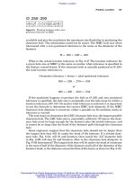
... Problem 3 First calculate the virtual and resultant conditions for the pin and the hole Then calculate the maximum and minimum distances for dimensions X and Y in Fig 7-17 The Virtual Condition ... Min Z The maximum and minimum distances between features Calculate the maximum and minimum distances for the dimensions X, Y, and Z in Fig 7-9 Start by calculating the virtual and the resultant ... actual feature size and its MMC Bonus tolerance for a particular feature is added directly to the geometric tolerance to equal the total tolerance for that feature Shift tolerance for a single feature...
Ngày tải lên: 05/08/2014, 09:20

Geometric Dimensioning and Tolerancing for Mechanical Design Part 7 ppt
... Problem 3 First calculate the virtual and resultant conditions for the pin and the hole Then calculate the maximum and minimum distances for dimensions X and Y in Fig 7-17 The Virtual Condition ... Min Z The maximum and minimum distances between features Calculate the maximum and minimum distances for the dimensions X, Y, and Z in Fig 7-9 Start by calculating the virtual and the resultant ... actual feature size and its MMC Bonus tolerance for a particular feature is added directly to the geometric tolerance to equal the total tolerance for that feature Shift tolerance for a single feature...
Ngày tải lên: 05/08/2014, 09:20
Geometric Dimensioning and Tolerancing for Mechanical Design Part 8 ppt
... than floating fasteners The formula for fixed fasteners is: t1 + t2 = H − F or H = F + t1 + t2 Where t1 is the tolerance for the threaded hole at MMC, t2 is the tolerance for the clearance hole at ... diameter at MMC, and F is the fastener diameter at MMC This formula is sometimes expressed in terms of 2T instead of t1 + t2 ; however, 2T implies that the tolerances for the threaded and the clearance ... zones for through and blind holes Figure 8-7 When specifying a projected tolerance zone for a through hole, place a circle P in the feature control frame after the material condition symbol, and...
Ngày tải lên: 05/08/2014, 09:20

Geometric Dimensioning and Tolerancing for Mechanical Design Part 8 potx
... than floating fasteners The formula for fixed fasteners is: t1 + t2 = H − F or H = F + t1 + t2 Where t1 is the tolerance for the threaded hole at MMC, t2 is the tolerance for the clearance hole at ... diameter at MMC, and F is the fastener diameter at MMC This formula is sometimes expressed in terms of 2T instead of t1 + t2 ; however, 2T implies that the tolerances for the threaded and the clearance ... zones for through and blind holes Figure 8-7 When specifying a projected tolerance zone for a through hole, place a circle P in the feature control frame after the material condition symbol, and...
Ngày tải lên: 05/08/2014, 09:20
Geometric Dimensioning and Tolerancing for Mechanical Design Part 9 ppsx
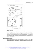
... requirement and a condition for the datums in the lower segment of the composite positional tolerancing feature control frame They: (Assume plane surface datums for question numbers 24 and 25.) ... Counterbore: Problems 16 and 17 16 Tolerance the holes and counterbores in Fig 8-31 for four Ø 250 socket head cap screws The counterbores are Ø 422 ± 010, the depth is 395 ± 010, and the geometric ... and runout is specified for high-speed rotating assemblies Many people erroneously specify a concentricity tolerance for the control of coaxiality, perhaps because they use the terms coaxial and...
Ngày tải lên: 05/08/2014, 09:20

Geometric Dimensioning and Tolerancing for Mechanical Design Part 10 pdf
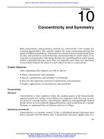
... 23:3 Concentricity and Symmetry Concentricity and Symmetry 173 The concentricity tolerance is independent of both size and form Differential measurement excludes size, shape, and form while controlling ... side of the center plane, and half is on the other side The symmetry tolerance is independent of both size and form Differential measurement excludes size, shape, and form while controlling the ... Concentricity is appropriately used for large, expensive parts that must have a small coaxial tolerance for balance but need not have the same small tolerance for form and surface imperfections Concentricity...
Ngày tải lên: 05/08/2014, 09:20
Geometric Dimensioning and Tolerancing for Mechanical Design Part 10 ppsx
... 23:3 Concentricity and Symmetry Concentricity and Symmetry 173 The concentricity tolerance is independent of both size and form Differential measurement excludes size, shape, and form while controlling ... side of the center plane, and half is on the other side The symmetry tolerance is independent of both size and form Differential measurement excludes size, shape, and form while controlling the ... Concentricity is appropriately used for large, expensive parts that must have a small coaxial tolerance for balance but need not have the same small tolerance for form and surface imperfections Concentricity...
Ngày tải lên: 05/08/2014, 09:20