ac motor control wiring diagram
Electrical wiring diagram
... 2118 123 456 1 23 12 11 12 1 2 123 45 678 12 12 A 1 BLACK A 2 GRAY A 3 GRAY A 4 DARK GRAY A 5 A10 GRAY A11 GRAY A13 BLACK A14 BLACK A15 A33 BLACK A32 GRAY A18 BLACK A19 A23 A25 YELLOW A26 YELLOW A27 BLACK A29 BLACK A30 A31 GRAY A46 BLACK A45A44 BLACK A42 ORANGE A41 ORANGE A40 ORANGE A36 GRAY A35 BLACK A47 ( LHD ) A47 ( RHD ) A48 GRAY A49 ... 4 BLACK 1 2 3456 12 345678 12 3456 1 2 3456 132 R 9 BLUE R 7 BROWN R 6 BLACK R 5 BLACK R 3 BLACK 7 12 34 56 8 910 11 12 12 3456 1 2 12 12 345 123 R10 R12 BLACK R13 BLACK R16 BLACK R17 S 1 BLACK ... A31 GRAY A46 BLACK A45A44 BLACK A42 ORANGE A41 ORANGE A40 ORANGE A36 GRAY A35 BLACK A47 ( LHD ) A47 ( RHD ) A48 GRAY A49 A50 A51 BLACK A52 A53 BLACK C 1 BLACK B11 GRAY B 6B 4 BLACK ( RHD ) B 4 BLACK ( LHD ) B...
Ngày tải lên: 13/10/2012, 08:47

2007 Toyota RAV4 Electrical Wiring Diagrams (EWD)
... Electrical Wiring Routing sections to find each part, junction block and wiring harness connectors, wiring harness and wiring harness connectors and ground points of each system circuit. Internal wiring ... circuit for each system. The actual wiring of each system circuit is shown from the point where the power source is received from the battery as far as each ground point. (All circuit diagrams are ... Anti–Lock Brake System ACIS = Acoustic Control Induction System CAN = Controller Area Network CPU = Central Processing Unit ECU = Electronic Control Unit EPS = Electric Motor Power Steering ESA...
Ngày tải lên: 22/10/2012, 10:20

Tài liệu Caterpillar C15 wiring diagram
... VALVE ACTUATOR 1 J-C6 INJECTOR 5 E-C2 INJECTOR 6 E-C3 5&6 RETARDER SOLENOID E-C8 INTAKE VALVE ACTUATOR 3 E-C4 INTAKE VALVE ACTUATOR 4 E-C5 INTAKE VALVE ACTUATOR 5 E-C6 INTAKE VALVE ACTUATOR ... machine. Ground (Case): This indicates that the component does not have a wire connected to ground. It is grounded by being fastened to the machine. Reed Switch: A switch whose contacts are controlled ... 180-9339 ACCESSORY TABLE QTY PART NAME P/N 1 RECEPTACLE AS. 3E-3370 1 WEDGE 3E-3371 200mm PAINT/PRO 110-3202 A-C14 CLR-GA WIRE NAME POS TERM/PLUG BU-18 T855-A34 1 180-9340 YL-18 H807-A35 2 180-9340 ACCESSORY...
Ngày tải lên: 24/10/2012, 16:57

Using Toyota Wiring Diagram P1
... USING THE ELECTRICAL WIRING DIAGRAM USING TOYOTA WIRING DIAGRAMS Page 1 © Toyota Motor Sales, U.S.A., Inc. All Rights Reserved. USING TOYOTA WIRING DIAGRAMS Page 12 â Toyota Motor Sales, U.S.A., ... WIRING DIAGRAMS Page 8 â Toyota Motor Sales, U.S.A., Inc. All Rights Reserved. USING TOYOTA WIRING DIAGRAMS Page 9 â Toyota Motor Sales, U.S.A., Inc. All Rights Reserved. USING TOYOTA WIRING ... Rights Reserved. USING TOYOTA WIRING DIAGRAMS Page 22 â Toyota Motor Sales, U.S.A., Inc. All Rights Reserved. USING TOYOTA WIRING DIAGRAMS Page 2 â Toyota Motor Sales, U.S.A., Inc. All Rights...
Ngày tải lên: 23/10/2013, 09:15

Design and Implementation of a Three-Phase Induction Motor Control Scheme
... detect the outputs of an induction motor, we can use this motor controller to control an induction machine. ã TMS320F243 DSP controller. This is manufactured by the Texas Instruments Company ... drawn by the induction motor form the feedback portion of the design. Hence, the major aim of this thesis project is to develop a control strategy for the DSP controller that controls the torque ... Roberts 4. The Induction Machine 4.1 The fundamental operating principles for an induction motor An induction motor is an asynchronous AC (alternating current) motor. The least expensive...
Ngày tải lên: 27/10/2013, 23:15

Tài liệu Using Toyota Wiring Diagram P2 doc
... USING THE ELECTRICAL WIRING DIAGRAM USING TOYOTA WIRING DIAGRAMS Page 1 © Toyota Motor Sales, U.S.A., Inc. All Rights Reserved. USING TOYOTA WIRING DIAGRAMS Page 22 â Toyota Motor Sales, U.S.A., ... WIRING DIAGRAMS Page 4 â Toyota Motor Sales, U.S.A., Inc. All Rights Reserved. USING TOYOTA WIRING DIAGRAMS Page 5 â Toyota Motor Sales, U.S.A., Inc. All Rights Reserved. USING TOYOTA WIRING ... DIAGRAMS Page 7 â Toyota Motor Sales, U.S.A., Inc. All Rights Reserved. USING TOYOTA WIRING DIAGRAMS Page 3 â Toyota Motor Sales, U.S.A., Inc. All Rights Reserved. USING TOYOTA WIRING DIAGRAMS ...
Ngày tải lên: 12/12/2013, 11:15

Tài liệu RANGER WIRING DIAGRAMS P2 pdf
... ENGINE 40 CONTROL SYSTEM MASS AIR FLOW SENSOR/ INTAKE AIR TEMPERATURE SENSOR No.2 [BLACK] 0140-208 [BLACK] FUEL INJECTOR No.4 0140-215 [BLACK] FUEL INJECTOR No.3 0140-214 FUEL INJECTOR No.1 [BLACK] 0140-212 FUEL ... No.1 [BLACK] 0140-115 ENGINE COOLANT TEMPERATURE SENSOR [GRAY] 0140-114 JOINT CONNECTOR C-25 0140-118 [BLACK] ACCELERATOR PEDAL POSITION SENSOR 0140-101 PCM 40 Form No. F1A1-10-05L CONTROL SYSTEM ... F1A1-10-05L CONTROL SYSTEM (WL-3) 0140-1b 46 Form No. F1A1-10-05L CONTROL SYSTEM (WL-C, WE-C) 0140-2c 42 Form No. F1A1-10-05L CONTROL SYSTEM (WL-C, WE-C) 0140-2a 44 Form No. F1A1-10-05L CONTROL...
Ngày tải lên: 13/12/2013, 00:15


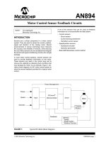
Motor control sensor feedback circuits
... Technology Inc. BACK EMF CONTROL METHOD The back electro-magnetic-force (EMF) or sensorless motor control method obtains the speed and position of the motor directly from the voltage at the motor windings. ... conditions that may damage the motor. As an example, Figure 1 pro- vides a block diagram of a DC motor control system to show the sensor feedback provided for a typical motor control. A list of the sensors ... efect tachometer ã Back EMF/Sensorless control method FIGURE 1: Typical DC Motor Block Diagram. Author: Jim Lepkowski Microchip Technology Inc. Power Management Input Microcontroller Driver Motor Feedback Torque Speed Direction Current Sensor Sensors *...
Ngày tải lên: 03/01/2014, 18:55


Tài liệu Ranger Wiring Diagrams P2 ppt
... VALVE [BROWN] 0140-219 CAMSHAFT POSITION SENSOR [BLACK] 0140-218 FUEL PRESSURE SENSOR [BLACK] 0140-216 EGR CONTROL SOLENOID VALVE [GREEN] 0140-220 [BLACK] PCM 0140-201 46 Form No. F1A1-10-05L CONTROL SYSTEM (WL-C, WE-C) ... ENGINE 40 CONTROL SYSTEM MASS AIR FLOW SENSOR/ INTAKE AIR TEMPERATURE SENSOR No.2 [BLACK] 0140-208 [BLACK] FUEL INJECTOR No.4 0140-215 [BLACK] FUEL INJECTOR No.3 0140-214 FUEL INJECTOR No.1 [BLACK] 0140-212 FUEL ... CONTROL SYSTEM EGR SOLENOID VALVE [BLACK] 0140-221 [BLACK] VARIABLE BOOST CONTROL SOLENOID VALVE 0140-222 [GRAY] EGR VALVE POSITION SENSOR 0140-217 VARIABLE SWIRL CONTROL SOLENOID VALVE [BROWN] 0140-219 CAMSHAFT...
Ngày tải lên: 23/01/2014, 04:20