2—regression analysis with error mandel 1984
Engineering Analysis with Ansys Software Episode 2 Part 1 potx
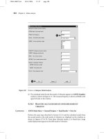
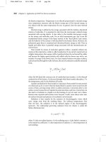
... 4.3 Mode analysis of a suspension for Hard-disc drive A B Figure 4.70 Window of Plot Deformed Shape Figure 4.71 The first mode of vibration 185 186 Chapter Mode analysis Figure 4.72 ... of vibration 4.3 Mode analysis of a suspension for Hard-disc drive Figure 4.74 The fourth mode of vibration Figure 4.75 The fifth mode of vibration 187 188 Chapter Mode analysis Figure 4.76 4.4 ... Mode analysis Figure 4.82 Window of Define Material Model Behavior A B Figure 4.83 Window of Create Keypoints in Active Coordinate System 4.4.2.3 CREATE KEYPOINTS To draw the moving table for analysis, ...
Ngày tải lên: 06/08/2014, 11:21
Engineering Analysis with Ansys Software Episode 2 Part 2 ppt
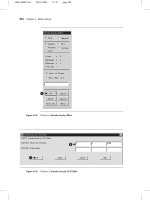
... Analysis 4.4.3.1 DEFINE THE TYPE OF ANALYSIS The following steps are performed to define the type of analysis Command ANSYS Main Menu → Solution → Analysis Type → New Analysis The window New Analysis ... left blank Chapter Analysis for Fluid Dynamics Chapter outline 5.1 5.2 5.3 5.1 Introduction Analysis of flow structure in a diffuser Analysis of flow structure in a channel with a butterfly valve ... 215 216 Chapter Analysis for fluid dynamics 5.2 5.2.1 Analysis of flow structure in a diffuser Problem description Analyze the flow structure of an axisymmetric conical diffuser with diffuser angle...
Ngày tải lên: 06/08/2014, 11:21
Engineering Analysis with Ansys Software Episode 2 Part 3 pot
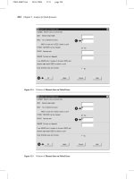
... the x-axis 5.3.2 Create a model for analysis 5.3.2.1 Command SELECT KIND OF ANALYSIS ANSYS Main Menu → Preferences 5.3 Analysis of flow structure in a channel with a butterfly valve 5.3.2.2 Command ... Path Items Figure 5.41 Window of PRPATH Command 242 Chapter Analysis for fluid dynamics 5.3 Analysis of flow structure in a channel with a butterfly valve 5.3.1 Problem description Analyze the flow ... shown in Figure 5.32 236 Chapter Analysis for fluid dynamics A B Figure 5.31 Window of Vector Plot of Predefined Vectors Figure 5.32 ANSYS Graphics window 5.2 Analysis of flow structure in a diffuser...
Ngày tải lên: 06/08/2014, 11:21
Engineering Analysis with Ansys Software Episode 2 Part 4 pps
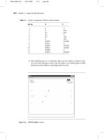
... button 250 Chapter Analysis for fluid dynamics A Figure 5.52 Window of Apply PRES on lines B C Figure 5.53 Window of Apply PRES on lines 5.3 Analysis of flow structure in a channel with a butterfly ... Analysis of flow structure in a channel with a butterfly valve Figure 5.60 Enlarged view near the valve in ANSYS Graphics window A B Figure 5.61 Window of Vector Arrow Scaling 257 258 Chapter Analysis ... (2) Input [A] 0.01 to VX box and [B] to VY box Then, click [C] OK button 5.3 Analysis of flow structure in a channel with a butterfly valve 249 A B C Figure 5.51 Window of Apply VELO load on lines...
Ngày tải lên: 06/08/2014, 11:21
Engineering Analysis with Ansys Software Episode 2 Part 5 potx
... walls Problem description A furnace with dimensions of its cross-section specified in Figure 6.1 is constructed from two materials The inner wall is made of concrete with a thermal conductivity, kc ... conductivity, kc = 0.01 W/m K The outer wall is constructed from bricks with a thermal conductivity, kb = 0.0057 W/m K The temperature within the furnace is 673 K and the convection heat transfer coefficient ... Preferences: Thermal A Figure 6.3 Element Types selection Depending on the nature of analysis to be attempted an appropriate analysis type should be selected In the problem considered here [A] Thermal...
Ngày tải lên: 06/08/2014, 11:21
Engineering Analysis with Ansys Software Episode 2 Part 6 pptx
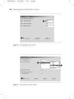
... Main Menu select Solution → Analysis Type → New Analysis Figure 6.62 shows the resulting frame Activate [A] Steady-State button Next, select Solution → Analysis Type → Analysis Options In the resulting ... tank with the pipe and then removing the internal part of the pipe using Boolean operation Boundary temperatures along with the convection coefficients and bulk fluid temperatures are dealt with ... select [A] Program chosen option 6.3 Steady-state thermal analysis of a pipe intersection 299 A Figure 6.62 New Analysis window A Figure 6.63 Analysis Options In order to set starting temperature...
Ngày tải lên: 06/08/2014, 11:21
Engineering Analysis with Ansys Software Episode 2 Part 7 docx
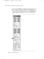
... Figure 6.103 Volume attributes with specified material and element type A Figure 6.104 Mesh Volumes 6.4 Heat dissipation through ribbed surface Figure 6.105 View of the fin with mesh network A Figure ... the pull down menu select [A] Cylindrical and click [B] OK button to implement the selection The analysis involves nodes located on inner surface of the pipe In order to include this subset of ... The values inputted are taken from Table 6.1 The final action is to select all entities involved with a single command Therefore, from Utility Menu select Select → Everything For the loads to be...
Ngày tải lên: 06/08/2014, 11:21
Engineering Analysis with Ansys Software Episode 2 Part 8 pot
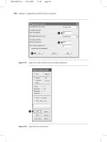
... problem This is a 3D analysis but because of the inherent symmetry of the model, analysis will be carried out for a quarter-symmetry model only There are two objectives of the analysis The first ... contact In a ball bearing, the ball makes point contact with the inner and outer races, whereas in a roller bearing the roller makes line contact with both the races Line contact arises when the profiles ... elements) becomes too large With metallic elements this restriction is ensured by the small strains at which the elastic limit is reached However, a different situation arises with compliant elastic...
Ngày tải lên: 06/08/2014, 11:21

Engineering Analysis with Ansys Software Episode 2 Part 9 pot
... be constrained with the displacement value equal to zero (see Figure 7.31) Clicking [B] OK button applies the constraints Because the original problem formulation asks for stress analysis when ... the pin, the analysis involves a large displacement effects The first type of load results from the interference fit between the pin and the arm From ANSYS Main Menu select Solution → Analysis Type ... Figure 7.35 Apply U,ROT on Nodes Options for the analysis of pull-out operation have to be defined now From ANSYS Main Menu select Solution → Analysis Type → Sol’n Controls The frame shown in...
Ngày tải lên: 06/08/2014, 11:21
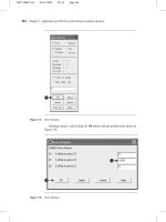
Engineering Analysis with Ansys Software Episode 2 Part 10 pdf
... is a 3D analysis and advantage could be taken of the inherent symmetry of the model Therefore, the analysis will be carried out on a quarter-symmetry model only The objective of the analysis ... by 0.05 cm, in order to create interference load, the analysis involves a large displacement effects From ANSYS Main Menu select Solution → Analysis Type → Sol’n Controls The frame shown in Figure ... half-symmetry model, shown in Figure 7.50, is finally created 7.2.2.3 MATERIAL PROPERTIES Before any analysis is attempted, it is necessary to define properties of the material to be used From ANSYS...
Ngày tải lên: 06/08/2014, 11:21

Engineering Analysis with Ansys Software Episode 2 Part 11 ppt
... head width = cm; head thickness = 0.5 cm; and rail height = cm Both elements are made of steel with Young’s modulus = 2.1 × 10⁹ N/m2 , Poisson’s ratio = 0.3 and are assumed elastic Friction coefficient ... the interface between cylinder and the rail is 0.1 7.2.3.2 MODEL CONSTRUCTION For the intended analysis a quarter-symmetry model is appropriate It is shown in Figure 7.93 The model is constructed ... ANSYS Main Menu select Preprocessor → Modelling → Create → Areas → Rectangle → By Dimensions Frame with entered coordinates, [A] (X1 = 1; X2 = 2) and [B] (Y1 = −0.5; Y2 = −1.5), is shown in Figure...
Ngày tải lên: 06/08/2014, 11:21

Engineering Analysis with Ansys Software Episode 2 Part 12 pps
... pull down menu); [B] By Elem Name (second pull down menu); and [C] Element Name = 174 The element with the number 174 was introduced automatically during the process of creation of contact pairs ... 7.135 implements the selections made From Utility Menu select Plot → Elements Image of the cylinder with mesh of elements is produced (see Figure 7.136) 406 Chapter Application of ANSYS to contact ... applied to the model C A B D Figure 7.130 Viewing Direction 7.2 Figure 7.131 Quarter symmetry model with elements, constraints, and loads A B Figure 7.132 Read Results by Load Step Number Example...
Ngày tải lên: 06/08/2014, 11:21
Engineering Analysis with Ansys Software Episode 2 Part 13 doc
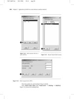
... Menu select Solution → Analysis Type: Sol’n Controls In response, the frame shown in Figure 7.191 appears As shown in Figure 7.191, the following selections are made: Analysis Options = Large ... shown in Figure 7.139 Next, the groove and the wall elements are to be created using existing nodes with numbers from 401 to 406 From ANSYS Main Menu select Preprocessing → Modelling → Create → Elements ... the wall and the groove for which LINK1 was selected as the element type at the beginning of the analysis Now, the nodal components are going to be created Figure 7.174 O-ring as a component From...
Ngày tải lên: 06/08/2014, 11:21

Engineering Analysis with Ansys Software Episode 2 Part 14 pps
... Entities (contact elements, Type 2, unselected) From ANSYS Main Menu select Preprocessor → Solution → Analysis Type → Sol’n Controls As a result of this selection, a frame shown in Figure 7.212 appears ... Main Menu select Solution → Solve → Current LS The frame shown in Figure 7.198 appears together with another frame, which gives a summary of solution options selected After checking the correctness ... volumes, 37, 364 Meshing, 152, 273 process, 396 Method of weighted residuals, 1, 2, 7, 35 Modal Analysis, 157 Mode I, 106, 116, 118, 119 Mooney-Rivlin, 412, 416 Move volume, 337 Moving table,...
Ngày tải lên: 06/08/2014, 11:21

Báo cáo khoa học: "Weak expression of cyclooxygenase-2 is associated with poorer outcome in endemic nasopharyngeal carcinoma: analysis of data rom randomized trial between radiation alone versus concurrent chemo-radiation (SQNP-01)" pdf
... median overall survival for patients with tumours with negligible or weak COX-2 expression was 5.3 years, while it was not achieved for patients with tumours with moderate or strong COX-2 expression: ... strong staining For the purpose of statistical analysis, the cohort was grouped into tumors with negligible or weak staining (N = 34) versus tumors with moderate or strong staining (N = 24) as ... followed by blockage of endogenous Statistical analysis Student's t-test was used to compare the age between patients with COX-2 IHC and those without COX-2 IHC Similarly, Fisher's exact test...
Ngày tải lên: 09/08/2014, 10:20

OReilly.Building.a.Web.2.0.Portal.with.ASP.NET.3.5.Jan.2008-BBL
... populates the user profile with default values, creates some default pages, populates them with specific widgets, etc Such compound operations are very easy to build with workflows, which enable ... Portal with ASP.NET 3.5 Other Microsoft NET resources from O’Reilly Related titles NET Books Resource Center C# 3.0 Cookbook™ C# 3.0 Design Patterns C# 3.0 in a Nutshell Learning ASP.NET 2.0 with ... free Building a Web 2.0 Portal with ASP.NET 3.5 Omar AL Zabir Beijing • Cambridge • Farnham • Köln • Paris • Sebastopol • Taipei • Tokyo Building a Web 2.0 Portal with ASP.NET 3.5 by Omar AL Zabir...
Ngày tải lên: 15/11/2012, 14:24

A new approach to semantic and syntactic functions of English adjectives – A contrastive analysis with their Vietnamese equivalents
... be used with a possessive s The problems of the poor or poor peoples problem is not correct grammatically Some adjectives used without the as head of a noun phrase in paired structures with and ... syntactic functions are also classified clearly in the chapter III, 3.3 With the contrastive analysis of English adjectives with their equivalents, basing on new approaches the writer has pointed ... deals with the semantic and syntactic functions of English adjectives, especially the classification of adjective semantic features in terms of their usage as well as presents a contrastive analysis...
Ngày tải lên: 10/04/2013, 14:46

engineering analysis with ansys software
... Engineering Analysis With ANSYS Software This page intentionally left blank Engineering Analysis With ANSYS Software Y Nakasone and S Yoshimoto Department ... 211 Chapter Analysis for fluid dynamics 5.1 5.2 Introduction Analysis of flow structure in a diffuser 5.2.1 5.2.2 Problem description Create a model for analysis 5.2.2.1 Select kind of analysis 5.2.2.2 ... path operation Analysis of flow structure in a channel with a butterfly valve 5.3.1 5.3.2 5.3.3 5.3.4 5.3.5 Problem description Create a model for analysis 5.3.2.1 Select kind of analysis 5.3.2.2...
Ngày tải lên: 17/08/2013, 11:58