1 design external forces

The Overseas Coastal Area Development Institute of Japan pptx
... 16 1 10 .3 Prediction of Beach Deformation 16 3 -iv- CONTENTS Chapter 11 Subsoil 16 7 11 .1 Method of Determining Geotechnical Conditions 16 7 11 .1. 1 11 .1. 2 ... 27.5 29.9 32.3 32.3 38 .1 39.3 44.3 67 m 83 94 10 9 13 7 14 4 16 1 18 5 200 218 233 249 256 286 Full load draft (d) 3.9 m 4.9 5.6 6.5 8.2 8.6 9.6 11 .0 11 .8 12 .9 13 .7 14 .7 15 .1 16.9 Container ships Deadweight ... 485 11 .3 .1 11. 3.2 11 .3.3 11 .3.4 11 .4 11 .5 Layout and Dimensions 485 External Forces and Loads 485 Design of Piers 486 Design of Girder ...
Ngày tải lên: 27/06/2014, 18:20

Báo cáo hóa học: " Design of Uniformly Most Powerful Alphabets for HDF 2-Way Relaying Employing Non-Linear Frequency Modulations" ppt
... Α 1. 0 0.5 Im Α 1. 0 7: dmin Α 0.0 0.0 0.5 0.5 0.5 1. 0 1. 0 1. 0 1. 5 1. 5 1. 0 0.5 0.0 0.5 1. 0 1. 5 1. 5 1. 5 1. 0 0.5 0.0 Re Α (a) p = 0.5 1. 0 Re Α 1. 5 1. 5 1. 0 0.5 0.0 0.5 1. 0 1. 5 Re Α (b) p = Figure 14 ... 1. 0 Im Α QFSKΚ 1. 5 0.0 0.0 0.5 0.5 0.5 1. 0 1. 0 1. 0 1. 5 1. 5 1. 0 0.5 0.0 0.5 1. 0 1. 5 1. 5 1. 5 1. 0 0.5 Re Α 0.0 0.5 1. 0 1. 5 1. 5 1. 5 Re Α (a) 1. 0 0.5 0.0 0.5 1. 0 1. 5 Re Α (b) (c) Figure Parametric minimal ... Networking 2 011 , 2 011 :12 8 http://jwcn.eurasipjournals.com/content/2 011 /1/ 128 Binary CPM Κ REC: dmin Α 1. 5 Binary CPM Κ RC: dmin Α 1. 5 Page 11 of 18 0.5 0.5 1. 0 0.5 0.0 Im Α 1. 0 Im Α 1. 0 Im Α Binary...
Ngày tải lên: 20/06/2014, 22:20

Báo cáo hóa học: " Research Article Noniterative Design of 2-Channel FIR Orthogonal Filters" pptx
... H(z) = h1 H1 (z) + hL z1−L H1 − z 1 (48) Let us finally compute the power spectral response, also by making use of (33): P(z) = H(z) = h1 H1 (z) + hL z1−L H1 − z 1 = h2 + h2 L +2 h2 d + 2h1 hL Re ... following form: h = (h1 , −ah1 , ah4 , h4 ), they must have norm 1, and satisfy the DC condition: h2 + h2 1 = 1+ a (36) = h1 (1 − a) + h4 (1 + a) (1 − a) √ , + a2 h4 = (1 + a) √ + a2 h= √ d − ... ⎟ = −T a1 , , aL/2 1 ⎟ ⎠ ⎜ ⎜ ⎜ ⎜ ⎝ ⎞ ⎛ h2 h4 hL−2 ⎛ h3 ⎜ ⎟ ⎜ ⎟ ⎜ ⎟ = T a1 , , aL/2 1 ⎜ ⎟ ⎝hL−3 ⎠ hL 1 h1 h3 ⎞ ⎟ ⎟ ⎟, ⎟ ⎠ (10 ) hL−3 h4 ⎞ ⎜ ⎟ t⎜ ⎟ ⎜ ⎟ ⎜ ⎟ ⎝hL−2 ⎠ hL (11 ) M Elena...
Ngày tải lên: 22/06/2014, 23:20

ARNOLD, K. (1999). Design of Gas-Handling Systems and Facilities (2nd ed.) Episode 1 Part 2 doc
... 1. 9902 1. 9428 1. 8972 1. 85 31 204 98 204 ,67 2.0360 208 07 9826 60 70 80 90 10 0 11 09.5 11 13.7 11 17.9 11 22,0 11 26 .1 0 .14 71 0 .16 45 0 .18 16 0 ,19 84 0. 214 9 1. 810 6 1. 7694 1. 7296 1. 6 910 1. 6537 1. 9577 1. 9339 ... 902 984 .1 977,9 11 30.2 11 34.2 11 38 .1 142.0 14 5.9 0.2 311 0.2472 0.2630 0.2785 0,2938 1. 617 4 1. 5822 1, 5480 1. 514 7 1, 4824 1. 8485 1. 8293 1. 810 9 1. 7932 ! 7762 16 0 17 0 18 0 19 0 200 210 212 14 12 3 14 .696 ... 1 1 B.W.G Gauge Thickness In internal Area !n.2 Ft2 External Surface PerFf Length 22 24 26 27 18 20 22 24 16 18 20 22 12 13 14 15 16 17 18 19 20 10 11 12 13 14 15 16 17 18 20 10 11 12 13 14 15 ...
Ngày tải lên: 06/08/2014, 02:20
ARNOLD, K. (1999). Design of Gas-Handling Systems and Facilities (2nd ed.) Episode 2 Part 1 docx
... Btu/SCF 16 18 2 316 3 010 3708 $3.00/MMBtu SCF/Gallon Equivalent Value $/Gallon Equivalent Value $/Gallon 37.5 36.4 31. 8 27.7 0 .12 13 0 .16 86 0 .19 15 0.2054 0 .18 20 0.2529 0.2872 0.30 81 252 Design of ... Main Feed Number 200 -11 00 24-30 20-50 450-600 20-30 20-50 17 5-300 85 -16 0 24-30 2-60 20-50 16 -60 550-650 350-500 200-300 70 -10 0 14 -30 10 -70 17 -70 18 -70 26-30 20-70 18 -70 15 -70 towers packing is ... ASTMD- 18 37- 81 2.5 — — 2,5 ASTMD-2 16 3-82 2.0 2.0 — ASTM D-2 16 3-82 — — — — ASTMD-2 15 8-80 ASTM D- 21 58-80 ASTMD- 18 38-84 ASTM D-2784-80I GPA Propane Dryness Test (Cobalt Bromide) or D-27 13 - 81 —...
Ngày tải lên: 06/08/2014, 02:20

ARNOLD, K. (1999). Design of Gas-Handling Systems and Facilities (2nd ed.) Episode 2 Part 2 pps
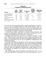
... machines Figure 10 -7 shows a typical vane compressor The operation is similar to that of a vane pump shown schematically in Figure 10 -10 of Volume 1, 2nd Edition (Figure 10 -9 in 1st Edition) A ... only) 10 20 2.0 2.7 2,7 ! 3 440 980 3,920 High Speed High Speed Centrifugal 10 0 2 2.7 2.0 2.0 2.0 2 19 ,602 88 19 0 380 Centrifugal Screw High Speed High Speed High Speed Screw 4.0 3.0 3.0 2 14 3 ... type of drivers available, cost of fuel, availability of spare 272 Design of GAS-HANDLING Systems and Facilities Figure 10 -11 Curve for estimating compression horsepower (Reprinted wirfi permission...
Ngày tải lên: 06/08/2014, 02:20
ARNOLD, K. (1999). Design of Gas-Handling Systems and Facilities (2nd ed.) Episode 2 Part 3 potx
... market, there are three common types of valves—poppet valves (Figure 11 -16 ), ring valves (Figure 11 -17 ), and plate valves (Figure 11 -18 ) Poppet valves are typically used for low compression ratio applications, ... Compressors 295 Figure 11 -9 API type distance pieces (Reprinted with permission from API, Std 618 , 3rd Ed., Feb 19 86.) 296 Design of GAS-HANDLING Systems and Facilities Figure 11 -10 The crosshead converts ... shown in Figure 11 -12 , oil enters into the bearing from supply holes strategically placed along the bearing circumference and builds up an oil Reciprocating Compressors 297 Figure 11 -11 Piston rings...
Ngày tải lên: 06/08/2014, 02:20
ARNOLD, K. (1999). Design of Gas-Handling Systems and Facilities (2nd ed.) Episode 2 Part 4 pdf
... 650°F 10 0°F 3,800 15 ,000 16 ,300 17 ,500 11 ,300 12 ,500 13 ,800 12 ,700 13 ,800 13 ,800 15 ,000 15 ,000 15 ,000 13 ,900 7,500 16 ,300 18 ,800 17 ,700 17 ,700 17 ,400 16 ,300 17 ,500 16 ,300 17 ,500 11 ,200 — 12 ,300 10 ,200 ... 10 ,200 18 ,300 20,000 21 700 23,300 15 ,000 16 ,700 18 ,10 0 6,900 18 ,300 18 ,300 20,000 20,000 20,000 20,000 23,300 21, 700 25,000 25,000 25,000 25.000 21. 700 23,300 21, 700 23,300 20,000 16 ,700 20,000 16 ,700 ... based on Table 12 -2 Summary ANSI Pressure Ratings Material Group 1. 1 MAWP, psig Class ~20°FtolOO°F 10 0°Fto200°F 15 0 300 400 600 900 15 00 2500 285 740 990 14 80 2220 3705 617 0 250 675 900 13 50 2025...
Ngày tải lên: 06/08/2014, 02:20

ARNOLD, K. (1999). Design of Gas-Handling Systems and Facilities (2nd ed.) Episode 2 Part 5 pps
... SA-333-6 SA -10 5 SA -18 1 -1 SA -19 3-B7 SA -19 4-2H SA -10 5 SA -18 1 -1 SA -19 3-B7M SA -19 4-2M SA-350-LF1 SA- 312 TP-304 SA -18 2 F-304 SA -19 3-B8 SA -19 4-8A SA- 312 TP- 316 L SA -18 2 F- 316 L SA -19 3-B8M SA -19 4-8MA SA-320-L7 ... head (0. 812 5) W = (0.34)(0. 812 5) (12 0)2 + (1. 9)(0. 812 5) (12 0) = 4 ,16 31b (c) Cone: _ Pd ~ cos a (SE - 0.6P) t t= (12 5) (12 0) • = 0.585 in (2 cos 30) (17 ,500 x 0.85 - 0.6 x 12 5) Required thickness = ... (0.875X120 )1= sin 30 (d) Skirt: Height = —— = 8.66 ft tan 30 Allow ft for access Height =11 ft Assume it is M-in plate W = (11 X120X0.5X 11) = 7,260 (e) Summary: Shell Head Cone Skirt Misc 12 ,870 4 ,16 3...
Ngày tải lên: 06/08/2014, 02:20

ARNOLD, K. (1999). Design of Gas-Handling Systems and Facilities (2nd ed.) Episode 2 Part 6 docx
... 1. 07 1. 08 1. 09 1. 10 1. 11 1 .12 1. 13 1. 14 1. 15 1. 16 1. 17 1. 18 1. 19 1. 20 1. 21 1.22 1. 23 1. 24 1. 25 1. 26 1. 27 1. 28 1. 29 1. 30 C k a 317 318 319 320 3 21 322 323 325 326 327 328 329 330 3 31 332 333 334 ... 339 340 3 41 342 343 344 345 346 347 1. 31 1.32 1. 33 1. 34 1. 35 1. 36 1. 37 1. 38 1. 39 14 1. 41 1.42 14 14 1. 45 14 14 14 14 1. 50 1. 51 1.52 1. 53 1. 54 1. 55 1. 56 1. 57 1. 58 1. 59 16 C 348 349 350 3 51 352 353 ... 3 61 362 363 364 365 365 366 367 368 369 369 370 3 71 372 373 k 1. 61 1.62 1. 63 J.64 1. 65 16 16 16 16 17 1. 71 1.72 1. 73 1. 74 1. 75 17 17 1. 78 1. 79 1. 80 1. 81 1.82 1. 83 1. 84 1. 85 18 1. 87 1. 88 1. 89 19 ...
Ngày tải lên: 06/08/2014, 02:20

ARNOLD, K. (1999). Design of Gas-Handling Systems and Facilities (2nd ed.) Episode 2 Part 7 docx
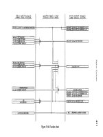
... evaluation (SAFE) chart for process flow in Figure 14 .5 {figure continued on pugf) Figure 14 *4, Continued Figure 14 *5 Simple process flow diagram 410 Design of GAS-HANDLING Systems and Facilities ... dis- Figure 14 -2 Hazard free for production facility (Source: API RP14.) * Indicates sources that can be anticipated by sensing changes in process conditions Figure 14 -2 Continued 392 Design of ... at 1, 480 psi If it is not properly designed and inspected, it may rupture before reaching 1, 480 psi pressure The primary defense to keep this from happening is to use the proper codes and design...
Ngày tải lên: 06/08/2014, 02:20
ARNOLD, K. (1999). Design of Gas-Handling Systems and Facilities (2nd ed.) Episode 2 Part 8 docx
... Al 05 ASTM A234, Grade WPB Sch 16 0 seamless Sch 80 seamless ASTM A105 ASTM A105 15 0 Ib ANSI FS RF screwed 15 0 Ib ANSI FS RF weld neck, bored to pipe schedule ASTM A105 Class fit, threaded over ... pressure class is assigned a designation Sometimes it is necessary to assign two classes for a single designation For example, in Table 15 -1 "A," "L," and "AA" are all ANSI 15 0 class, but they contain ... on-off valve (Figure 15 -1) A bore through the ball allows flow when it is lined up with the pipe and blocks flow when it Valves, Fittings, and Piping Details 427 Table 15 -1 Example Index of Pipe,...
Ngày tải lên: 06/08/2014, 02:20

ARNOLD, K. (1999). Design of Gas-Handling Systems and Facilities (2nd ed.) Episode 2 Part 9 ppt
... _ 11 26 -12 00 10 91- 1200 10 91- 1200 10 61- 1200 10 31- 117 0 10 01- 113 0 9 81- 112 0 9 71- 110 0 9 71- 110 0 9 61- 1090 9 51- 1080 9 01- 1 010 _ „ _ _ _ _ _ _ _ 11 71- 1200 11 31- 1200 11 21- 1200 11 01- 1200 11 01- 1200 10 91- 1200 ... 6 61- 880 8 81- 1200 16 0-640 6 41- 870 8 71- 1090 10 91- 1200 21A 16 0-620 6 21- 960 11 61- 1200 9 61- 116 0 16 0-600 6 01- 810 811 -10 00 10 01- 1200 16 0-600 6 01- 790 7 91- 970 9 71- 112 5 16 0-550 5 51- 740 7 41- 930 9 31- 1090 _ 16 0-740 ... 16 0-740 7 41- 900 9 01- 1090 10 7 51- 900 16 0-750 9 01- 1060 _ 12 16 0-740 9 01- 1030 7 41- 900 14 16 0-700 7 01- 850 8 51- 1000 16 16 0-690 6 91- 840 8 41- 980 _ 18 16 0-690 8 31- 970 6 91- 830 20 6 91- 830 16 0-690 8 31- 970 _...
Ngày tải lên: 06/08/2014, 02:20

ARNOLD, K. (1999). Design of Gas-Handling Systems and Facilities (2nd ed.) Episode 2 Part 10 pptx
... driven at 1A engine speed Figures 16 -1 and 16 -2 illustrate a cross section and an idealized P-V diagram for a four-cycle spark-ignited engine, respectively Prime Movers 469 Figure 16 -1 Cross section ... 40% range, Figure 16 -10 This schematic illustrates how waste heat can be recovered and used to heat process fluids 482 Design of GAS-HANDLING Systems and Facilities Figure 16 *11 The combined cycle ... As shown in Figures 16 -6 and 16 -7, the gas turbine consists of 478 Design of GAS-HANDLING Systems and Facilities Figure 16 -6 Schematic of single-shaft gas turbine Figure 16 -7 Cutaway view of...
Ngày tải lên: 06/08/2014, 02:20

ARNOLD, K. (1999). Design of Gas-Handling Systems and Facilities (2nd ed.) Episode 2 Part 11 ppsx
... 500.) 508 Design of GAS-HANDLING Systems and Facilities Figure 17 -10 Relief valve in a nonenclosed, adequately ventilated area (Reprinted with permission from AH RP 500.) Figure 17 -11 Ball or ... power of a circuit and is measured in VA or kVA (1, 000 VA) It is obtained by multiplying voltage and current Figure 17 -1 Three-phase connections 498 Design of GAS-HANDLING Systems and Facilities ... Electrical Systems Figure 17 -3 Hazardous area classifications used in U.S and Canada, in accordance with Article 500, NEC Code 19 84 (Courtesy of R Stahl, Inc.] 5 01 502 Design of GAS-HANDLING Systems...
Ngày tải lên: 06/08/2014, 02:20

ARNOLD, K. (1999). Design of Gas-Handling Systems and Facilities (2nd ed.) Episode 2 Part 12 pps
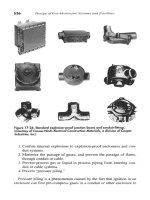
... Table 17 -2 Temperature Ratings of Explosion-Proof Enclosures Maximum Temperature °C °F 450 300 280 260 230 215 200 18 0 16 5 16 0 13 5 12 0 10 0 J*5 842 572 536 500 446 419 392 356 329 320 275 248 212 ... installation are provided for combustible gas detectors by ISA SI2 .13 and RP 12 .13 and for hydrogen sulfide gas detectors by ISA S12 .15 and RP 12 .15 Required locations of gas detectors (sensors) are often ... loosening Stems over 12 inches in length must be laterally braced within 12 inches of fixtures All portable lamps in Division areas must be explosion-proof Figures 17 -19 , 17 -20, and 17 - 21 show typical...
Ngày tải lên: 06/08/2014, 02:20
ARNOLD, K. (1999). Design of Gas-Handling Systems and Facilities (2nd ed.) Episode 2 Part 13 docx
... power supply, 517 Components compressors, 286-307 heavy, 13 7 intermediate, 11 1, 13 0 -13 1 ,13 5 ,13 7 ,14 9 light, 11 1, 13 1 -13 2, 13 5, 13 7 554 Compression engine, 470 gas, Compressor buildings, 514 horsepower, ... Coils, indirect heaters diameters, 11 7 -11 8 length, 11 9 -12 0 sizing, 11 6 -12 0 temperatures, 11 6 -11 7 wall thickness, 11 8 -11 9 Cold Bed Absorption (CBA) process, 17 4 Combustion gas turbine, 479,482 ... vibration, 317 - 319 volumetric efficiency, 308 Condensate, 3, 11 1 Condensate stabilization, 3, 13 0 -15 0 Condensate stabilizers cold feed, 11 1, 13 4, 13 6 -13 7, 14 9, 249 definition, 13 4 design, 13 7 gas-producing...
Ngày tải lên: 06/08/2014, 02:20

ARNOLD, K. (1999). Design of Gas-Handling Systems and Facilities (2nd ed.) Episode 2 Part 14 pot
... Sulfide-stress cracking, 18 1, 448 Sulfinol process, 17 1 -17 2 Sulfolane, 17 1 Sulfreen process, 17 4 Sulfur, 17 2 -17 4, 17 6 Sulfur compounds, 15 1 Sulfur dioxide, 17 0 ,17 2 -17 4, 17 6 Sulfuric acid, 15 1 567 Sumps, ... low-pressure, 13 1 ,14 9, 2 01 low-temperature, 11 0 -11 1 pressure, pump gas, 2 01 three-phase, 247 two-phase, 13 7 Service, seawater and brackish, 72 Set pressure, 4 41 Shell ADIP process, 16 6, 18 5 Shell-and-tube ... 516 Linde, A G., 17 2 Line heaters, 48, 10 9, 11 2 -11 3, 12 0 -12 2, 462 Liquefied petroleum gas (LPG), 17 8, 2 41, 246 Liquid bath, 28 dump valves, 11 1 flow rates, process, 445 glycol, 19 5 hydrocarbons,...
Ngày tải lên: 06/08/2014, 02:20

Bruhn - Analysis And Design Of Flight Vehicles Structures Episode 1 Part 2 pot
Ngày tải lên: 07/08/2014, 10:20

Bruhn - Analysis And Design Of Flight Vehicles Structures Episode 2 Part 1 pps
Ngày tải lên: 07/08/2014, 10:20