§ 2 1 energy entropy and availability balances

Biofuels, Solar and Wind as Renewable Energy Systems_Benefits and Risks Episode 1 Part 2 pps
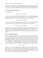
... 22 T.W Patzek 18 0 16 0 World Oil Production US Oil Consumption Petroleum, EJ/Year 14 0 12 0 10 0 80 60 27 0 billion gallons of ethanol per year 40 20 20 00 20 20 20 40 20 60 20 80 21 00 21 20 21 40 21 60 21 80 ... 2, 690 kgb 2, 690 kgb 15 ,000 Le kgg kgg kgg 2, 546, 000 kcali 3 92 kWhi kcal/Ll 20 kg BODm ◦ 3 31 kcal/L 2, 550b 322 c 90f 16 5h 92h 384h 2, 546i 1, 011 i 9l 69n 3 31 7,569 28 7.36 21 .40d 21 .16 f 10 .60d 10 .60d ... production rate, (HHV) EJ/year 10 3 1 02 10 1 10 0 10 1 1880 19 00 1 920 19 40 19 60 19 80 20 00 20 20 Fig 2. 3 Exponential growth of world crude oil production between 18 80 and 19 70 proceeded at 6.6% per year...
Ngày tải lên: 06/08/2014, 04:20
Biofuels, Solar and Wind as Renewable Energy Systems_Benefits and Risks Episode 2 Part 1 pot
... (1 – CR) = fraction of full crop rotation schedule that soybean is grown Disposition Overall 10 0 3 10 1 1 02 9 18 18 17 2 12 70 27 14 70 27 14 70 27 18 70 27 18 10 0 10 1 1 18 17 8 70 27 14 70 27 ... 10 +5 3.69 × 10 +6 3.43 × 10 +5 4.07 × 10 +5 2. 63 × 10 +5 1. 09 × 10 +5 1. 55 × 10 +5 2. 13 × 10 +5 1. 80 × 10 +5 1. 65 × 10 +5 nv 3.57 × 10 +5 nv 6.77 × 10 +6 1 .29 × 10 +6 ∗ With respect to k, n, pk , and ⌬k , see ... GGEjk values 14 13 48 7.55 × 10 +0 3.33 × 10 +3 7.84 × 10 +2 1. 12 × 10 +2 4 .23 × 10 +3 nv 6 .29 × 10 +2 1. 06 × 10 +2 nv 6.38 × 10 +2 out of 12 out of out of out of 15 a values obtained by using only non-duplicated...
Ngày tải lên: 06/08/2014, 04:20

Climate change as environmental and economic hazard - phần 2.1
... HAZARDS (20 09) 20 9 22 5 doi :10 .3763/ehaz .20 09.0 023 # 20 09 Earthscan ISSN: 17 47-78 91 (print), 18 78-0059 (online) www.earthscanjournals.com 21 0 Botzen and van den Bergh FIGURE Overall and insured ... Pierrehumbert, 20 04) The Intergovernmental Panel on Climate Change (IPCC) projects a rise in global average surface temperatures between 1. 1 and 2. 98C in 21 00 for a low-emission scenario and between 2. 4 and ... M., Van Vuuren, D., Den Elzen, M G J and Swart, R., 20 06 Multi-gas emissions pathways to meet climate targets Climatic Change, 75 (1) 15 1 – 19 4 RCEP, 20 00 Energy – the Changing Climate Royal Commission...
Ngày tải lên: 07/10/2012, 15:57
Tài liệu PRIVATE ENTREPRENEURS IN CHINA AND VIETNAM PART 2-1 ppt
... staff 8 -20 21 -50 51- 100 10 1 -20 0 20 1- 500 5 01- 1.000 1. 0 01 -2. 000 2. 000 Total Hangzhou Number % 12 17 .9 16 23 .9 16 23 .9 13 19 .4 10 .4 3.0 0.0 1. 5 67 10 0.0 Luohe Number % 13 21 .7 19 31. 7 16 26 .7 10 .0 ... Chemistry 10 Furniture 11 Toys 12 Metal goods 13 Mining 14 Others Total % Number % Number % 14 12 11 2 1 69 20 .3 17 .4 15 .9 13 .0 2. 9 10 .1 1.5 7 .2 2.9 2. 9 1. 5 1. 5 0.0 2. 9 10 0.0 4 11 30 0 1 0 60 6.7 ... Vietnam Number % 5.7 0.0 20 .0 11 .4 8.6 17 .1 0.0 5.7 2. 9 11 .4 8.6 2. 9 2. 9 2. 9 35 10 0 .1 South Vietnam Number % 1 .2 0.0 3.5 13 15 .1 20 23 .3 2. 3 1 .2 15 17 .4 8 .1 7.0 3.5 5.8 5.8 5.8 86 10 0.0 LOCALITIES;...
Ngày tải lên: 15/12/2013, 06:15

Tài liệu Ethernet 2 Lab Exercise 1 VLAN, Trunk, and EtherChannel Configuration docx
... Switch A 10 .1. 1 .1 /24 Switch B 10 .1. 1 .2/ 24 PC -1 10 .2. 1. 1 /24 PC -2 10 .2. 1 .2/ 24 PC-3 10 .3 .1 .2/ 24 Router 10 .3 .1. 1 /24 VTP Domain: lab VLAN name: vlan1 VLAN name: vlan2 VLAN name: vlan3 Part 1: VLANs and ... channel x1/y1-y2 [IE-LANS2-LS1-F04] [20 01- 04 -20 - 02] Copyright © 20 01 Genium Publishing Corporation http://www.certificationzone.com/studyguides /?Issue=36&IssueDate=05- 01 -20 01& CP= 11 /06/ 01 ... SwitchB(enable)set int sc0 10 .1. 1 .2 255 .25 5 .25 5.0 vtp domain lab mode client vlan x2/y5 vlan x2/y6 Router(config)#int fa x3/y7 Router(config-if)#ip address 10 .3 .1. 1 25 5 .25 5 .25 5.0 Part 2: EtherChannel Goals...
Ngày tải lên: 24/01/2014, 19:20
![Tài liệu Báo cáo khoa học: Specific targeting of a DNA-alkylating reagent to mitochondria Synthesis and characterization of [4-((11aS)-7-methoxy-1,2,3,11a-tetrahydro-5H-pyrrolo[2,1-c][1,4]benzodiazepin-5-on-8-oxy)butyl]-triphenylphosphonium iodide doc](https://media.store123doc.com/images/document/14/br/vp/medium_vpv1392870032.jpg)
Tài liệu Báo cáo khoa học: Specific targeting of a DNA-alkylating reagent to mitochondria Synthesis and characterization of [4-((11aS)-7-methoxy-1,2,3,11a-tetrahydro-5H-pyrrolo[2,1-c][1,4]benzodiazepin-5-on-8-oxy)butyl]-triphenylphosphonium iodide doc
... mmol, 14 %) 1H NMR d 7.6–7.9 (m (16 H, P+–ArH and H -11 ), 7.46 (1H, s, H-6), 6.49 (1H, s, H-9), 4 .1 4 .2 (2H, m, Ar-O-CH2), 3. 71 (3H, s, O-CH3), 3.4– 4.0 (5H, m, P+–CH2, H -11 a and H-3), 1. 75 2. 4 (8H, ... 1. 75 2. 4 (8H, m, O-CH2-CH2, P+–CH2-CH2, H -1 and H -2) p.p.m., 31 PNMR d 25 .65 p.p.m ESMS found (M+) 563 .24 69 calculated for C35H36O3N2P (M+) 563 .24 58 H (300 MHz) and 31P ( 12 1 MHz) NMR spectra were ... [4-( (11 aS)-7-methoxy -1 ,2, 3 ,11 a-tetrahydro-5H-pyrrolo [2, 1c] [1, 4]benzodiazepin-5-on-8-oxy)butyl]triphenylphosphonium iodide (2; mitoDC- 81) Materials and methods Synthesis of [4-( (11 aS )-7-methoxy -1 ,2, 3 ,11 a-tetrahydro5H-pyrrolo [2, 1- c] [1, 4]benzodiazepin-5-on-8-oxy)butyl]triphenylphosphonium...
Ngày tải lên: 20/02/2014, 11:20
Báo cáo khoa học: Glutathione transferases kappa 1 and kappa 2 localize in peroxisomes and mitochondria, respectively, and are involved in lipid metabolism and respiration in Caenorhabditis elegans pot
... elegans A 69 gstk -1 (zk1 320 .1) B AA position rGSTK1 GSTK -1 GSTK -2 4 62 51 150 1 82 15 1 gstk -2 (d2 024 .7) E Petit et al 380 599 50 469 10 0 15 0 20 0 C that C elegans ZK1 320 .1 and D2 024 .7 genes belong ... ⁄ VV) at the N-terminus of the GSTK -2 sequence For these reasons, ZK1 320 .1 and D2 024 .7 genes were renamed gstk -1 and gstk -2 50 32 14 7 Fig Genomic structure and intron positions in C elegans gst ... gstk -2( RNAi) gstk -1/ k -2( RNAi) * 18 16 Fig gstk -1 ⁄ gstk -2( RNAi) animals display an abnormal FAME composition Simplified FAME composition of control and gstk -1, gstk -2 and double gstk -1( RNAi) and...
Ngày tải lên: 16/03/2014, 03:20

Báo cáo khoa học: Crystal structures of the human SUMO-2 protein at 1.6 A and 1.2 A resolution ppt
... (2. 6) 4.6 (55.9) CNS 1. 1 7868 (633) 0 .16 9 (0 .26 6) 0 .19 0 (0 .27 3) 0. 017 1. 8 27 1. 3 97 .1 2. 9 17 .7/3 12 22. 8/ 322 34.3/67 SHELX-97 20 948 (1 924 ) 0 .11 9 (0 . 21 7) 0 .18 5 (0 .23 9) 0. 013 2. 3 26 1. 8 96.8 3 .2 ... 98.5 (85 .1) 45.5 (5.3) 3.9 (24 .6) R3 (hexagonal indexing) a ¼ b ¼ 74.96, c ¼ 33 .23 NSRRC BL17B2 1. 0 717 RAXIS-IV+ + 83.4 1. 5 0 .29 2 14 5 20 1 .2 (1 .24 1 .20 ) 14 14 02 (11 874) 21 7 81 ( 21 09) 10 0.0 (99.8) ... 17 –87 17 –87 17 –88 Water Resolution 38 67 67 1 02 1 02 12 7 3.0 2. 0 1. 6 1. 6 1. 5 1. 5 1 .2 1 .2 1 .2 ˚ A ˚ A ˚ A ˚ A ˚ A ˚ A ˚ A ˚ A ˚ A R/Rfree 0.464 0.339/0.3 71 0 .19 0/0 .22 4 0 .16 9/0 .19 0 0.409 0.375 0 .19 1/0 .20 5...
Ngày tải lên: 16/03/2014, 18:20
Báo cáo khoa học: Functional expression of the quinoline 2-oxidoreductase genes (qorMSL) in Pseudomonas putida KT2440 pUF1 and in P. putida 86-1 Dqor pUF1 and analysis of the Qor proteins doc
... CL-4B BioScale DEAE10 85.3 87.4 71. 9 36.5 3696 516 76 17 .4 0. 023 0 .17 0.95 2. 10 41 91 100 1 02 84 43 Conditions of Qor synthesis in wild-type P putida 86, P putida 86 -1 Dqor pUF1 and P putida 86 ... activity (UÆmg )1) Purification (-fold) Yield (%) Crude extract Ammonium sulfate ppt Phenyl Sepharose CL-4B BioScale DEAE10 3 12 2 71 29 9 20 6 3045 416 78 9.3 0 .10 0.65 3.83 22 .1 6.4 37.5 21 6.7 10 0 87 96 ... quinoline) P putida KT2440 pUF1 (grown on benzoate) P putida 86–1Dqor pUF1 (grown on benzoate + 1H -2- oxoquinoline) 0.8 0.08 5.5 5.4 1 .2 1. 3 0 .18 c 0. 12 74 8.7 0.5 1 .2 0. 12 85.4 a Average of two...
Ngày tải lên: 17/03/2014, 10:20
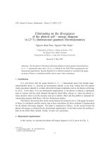
Báo cáo "Eliminating on the divergences of the photon self - energy diagram in (2+1) dimensional quantum electrodynamics " pot
... Γ (1 /2) = π , we have nf ΠM =4ie2 1 ci i=0 2 e k =− (2 ) 1 /2 dxx (1 − x) d3 p × 3 /2 − p2 )2 (2 ) (ai (22 ) co c1 c2 dxx (1 − x) + 1 /2 + 1 /2 , )1 /2 (ao (a1 ) (a2 ) where a2 = m2 − x (1 − x)k ; a2 = ... (2 ) 1 /2 dxx (1 − x) [m2 and consequently, 1 (0) = − x (1 − x)k ] 1 /2 , (24 ) From (20 ), we have : ΠM (k ) = e2 4mπ + dx m [m2 − x (1 − x)k ] (α − 1) M1 [M1 − x (1 − x)k ] 1 /2 − 1 /2 (25 ) (α − 1) M2 ... (2 ) 2pµ pν 2x (1 − x)kµkν 2x (1 − x)k gµν gµν im µνα k α − + − − 2 − a2 )2 − a2 )2 − a2 )2 (p (p (p p −a (p − a2 )2 Πµν (k) =2ie2 µ dx =2ie2 µ dx + dn p n (2 ) 2pµ pν gµν − 2 − a2 )2 (p (p − a2...
Ngày tải lên: 28/03/2014, 13:20

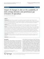
Báo cáo sinh học: " Impact of changes in diet on the availability of land, energy demand and greenhouse gas emissions of agriculture" pot
... Fruit production 11 1 24 5 24 5 24 5 1 42 1 42 1 42 Animal husbandry 2, 2 52 1, 146 1, 146 1, 146 1 ,29 4 1 ,29 4 1 ,29 4 Sum 4,005 2, 505 2, 648 2, 715 2, 5 31 2, 7 21 2, 75 where the additional energy crop production ... 726 460 595 595 550 724 724 Grassland 460 14 3 1 52 220 1 52 16 9 19 8 Animal feed crop cultivation 363 319 325 320 29 0 29 0 29 0 Vegetable production 99 19 0 19 0 19 0 1 02 1 02 1 02 Fruit production 11 1 ... import/export c Bioethanol [TJ] 4,8 62 4,8 62 1, 366 1, 366 Biogas [TJ] 3, 415 10 ,035 3 ,20 3 6,773 Sum [TJ] 8 ,27 9 14 ,897 4,577 8 ,14 1 CED [TJ] 21 ,530 22 ,0 91 22 ,11 5 22 ,359 38% 68% 21 % 37% Biodiesel [TJ] Proportion...
Ngày tải lên: 18/06/2014, 18:20

Renewable Energy Trends and Applications Part 2 docx
... (0.4 916 ) 376 0.6465 25 . 61* ** PCSE Model II -0.00 02* ** (0.0000) -0.79 72* ** (0.0436) -0 .25 63*** (0.0 316 ) -0.0086*** (0.0 011 ) -0. 613 7*** (0 .20 32) 2. 47 72* ** (0 .29 98) 1. 017 1*** (0.33 32) 2. 2 21 5*** (0 .15 49) ... LCRESct -1 IMPTDPct VOLGDPPCct Mean VIF VIF 4 . 21 3. 12 2.79 2. 25 1. 98 1. 69 1. 65 1. 15 2. 35 1/ VIF 0 .23 7790 0. 3 21 027 0.3586 31 0.4449 51 0.504358 0.5 929 46 0.604563 0.86 727 1 Table Variance Inflation Factor Once ... Observations R2/Pseudo R2 F (N(0 ,1) ) Wald ( 2) OLS Model I -0.00 02* ** (0.0000) -0.79 72* ** (0.04 12 ) -0. 025 6*** (0.0676) -0.0086*** (0.0 0 21 ) -0. 613 7* (0.3599) 2. 47 72* ** (0.7353) 1. 017 1** (0. 510 7) 2. 2 21 5***...
Ngày tải lên: 19/06/2014, 08:20
Energy Technology and Management Part 1 pot
... distributions 10 Energy Technology and Management Will-be-set-by-IN-TECH Γ [1; 1] [1; 2] [2; 1] [2; 2] Rc/t 1. 54% 1. 04% 1. 07% 1 .25 % Ru/w 11 . 51% 4.97% 12 . 24% 1. 67% RbB/B ,2 81. 37% 42. 32% 46.79% 49 .16 % P(W) ... 81. 37% 42. 32% 46.79% 49 .16 % P(W) 0. 610 9 0.5487 0.60 32 0.7470 R T/P (10 5 bpJ) 7 .15 78 7.9674 7 .23 16 5. 826 0 d1 (ms) 37.4 29 .8 81. 0 12 5 .4 d2 (ms) 32. 3 60.0 28 .0 61. 3 Table Simulation results for different ... accurately and effectively There are also other MATLAB-based IEEE8 02. 11 simulators, such as for IEEE8 02. 11 a (MATLAB Central, 20 03) and the PHY layer of IEEE8 02. 11 b (MATLAB Central, 20 09) Our simulator...
Ngày tải lên: 19/06/2014, 10:20

Energy Technology and Management Part 2 potx
... c =16 75. 52 71. 74 72. 27 70. 91 325 . 31 27 0.96 27 7.64 26 0.80 90 .18 87 .28 87.04 87 .10 4 .10 4.83 4.73 4.94 c =20 72. 98 72. 22 72. 14 70.33 28 6 .14 28 1. 65 28 1. 02 255.76 89 . 21 88 .11 88.43 88 .19 4. 32 6. 02 ... c=8 42. 17 44 .29 44 .20 44 .19 1 32. 72 13 8 .29 12 4 . 41 12 6 .80 95.59 85 .27 77. 41 77.69 34.58 32. 75 25 .23 26 .58 c= 12 44. 31 37.34 36. 01 35.65 17 4. 52 13 7.83 11 5 .23 11 4.65 93.39 85.56 77 . 21 77 .10 52. 88 ... β∗ (ms) 10 26 38 16 30 46 Γ∗ [2; 3] [1 ;2] [1 ;2] [1 ;2; 2] [1 ;2; 2] [1 ;2; 2] = 2ms and Θ Θ∗ [39; 31] [39; 31] [39; 31] [39; 31; 31] [39; 31; 31] [39; 31; 31] r∗ [0;0] [0;0] [0;0] [0;0 ;1] [0;0 ;1] [0;0 ;1] = 8)...
Ngày tải lên: 19/06/2014, 10:20
Clean Energy Systems and Experiences Part 1 ppt
... S2 Sm (b) Circuit when S is on D S1 Battery set D1 Sm D2 D S1 (c) Circuit when S1 is on S2 Sm D2 (d) Circuit when S1 and S2 are off Fig The dc/dc converter and its different stages Figure shows ... inverter (b) Multiple dc/dc converters and multilevel inverter Fig Topologies to inject current to the ac mains V1 V1 S1 S1 S3 S2 S4 V2 S2 V2 Sa Sc (a) Buck converter and buck-boost converter Sb Sd (b) ... applications D S1 Battery set Renewable source Battery set D1 S2 Renewable source (a) Analyzed converter Renewable source D D1 Sm Renewable source D2 D2 S1 Battery set D1 S2 S2 Sm (b) Circuit...
Ngày tải lên: 20/06/2014, 06:20

Clean Energy Systems and Experiences Part 2 potx
... (Bong (20 09); Chung (20 09); Doms (20 09); Eguchi (20 09a; 20 10 a;b); Gregoire (20 06); Min (20 02) ; Myono (20 01) ; Park (20 09); Starzyk (20 01) ; Tanzawa (19 97); Wei (20 08); Yamada (20 04); Yamakawa (20 08)) ... s1 x2 x1 1 u s1a b ki ( x2 x2 r ) (6) With expressions (5) and (6) existence conditions are: r0 w0 s1 x2 x1 r (7) A DC/DC converter for clean -energy applications 11 ... y x2 x2 r , ez x2 x2r , f (t ) a wo x2 (1 u ) , s1, kc and ki are the controller parameters The dc/dc boost converter model is: x1 a w0 x (1 u ) x b w0 x1 (1 u...
Ngày tải lên: 20/06/2014, 06:20
Báo cáo toán học: " Impact of changes in diet on the availability of land, energy demand, and greenhouse gas emissions of agriculture" docx
... production 11 1 24 5 24 5 24 5 1 42 1 42 1 42 Animal husbandry 2, 2 52 1, 146 1, 146 1, 146 1 ,29 4 1 ,29 4 1 ,29 4 Sum 4,005 2, 505 2, 648 2, 715 2, 5 31 2, 7 21 2, 75 CED [MJ/capita] where the additional energy crop production ... Grassland 726 460 460 14 3 595 1 52 595 22 0 550 1 52 724 16 9 724 19 8 Animal feed crop cultivation 363 319 325 320 29 0 29 0 29 0 Vegetable production 99 19 0 19 0 19 0 1 02 1 02 1 02 Fruit production 11 1 24 5 24 5 ... Steinmüller Energy, Sustainability and Society 20 11 , 1: 6 http://www.energsustainsoc.com/content /1/ 1/6 10 11 12 13 14 15 16 17 18 19 20 21 22 23 24 25 26 27 28 29 30 Carlsson-Kanyama A (19 98) Climate...
Ngày tải lên: 20/06/2014, 21:20

Clean Energy Systems and Experiences Part 1 pdf
... S2 Sm (b) Circuit when S is on D S1 Battery set D1 Sm D2 D S1 (c) Circuit when S1 is on S2 Sm D2 (d) Circuit when S1 and S2 are off Fig The dc/dc converter and its different stages Figure shows ... inverter (b) Multiple dc/dc converters and multilevel inverter Fig Topologies to inject current to the ac mains V1 V1 S1 S1 S3 S2 S4 V2 S2 V2 Sa Sc (a) Buck converter and buck-boost converter Sb Sd (b) ... applications D S1 Battery set Renewable source Battery set D1 S2 Renewable source (a) Analyzed converter Renewable source D D1 Sm Renewable source D2 D2 S1 Battery set D1 S2 S2 Sm (b) Circuit...
Ngày tải lên: 21/06/2014, 01:20

Clean Energy Systems and Experiences Part 2 docx
... (Bong (20 09); Chung (20 09); Doms (20 09); Eguchi (20 09a; 20 10 a;b); Gregoire (20 06); Min (20 02) ; Myono (20 01) ; Park (20 09); Starzyk (20 01) ; Tanzawa (19 97); Wei (20 08); Yamada (20 04); Yamakawa (20 08)) ... s1 x2 x1 1 u s1a b ki ( x2 x2 r ) (6) With expressions (5) and (6) existence conditions are: r0 w0 s1 x2 x1 r (7) A DC/DC converter for clean -energy applications 11 ... y x2 x2 r , ez x2 x2r , f (t ) a wo x2 (1 u ) , s1, kc and ki are the controller parameters The dc/dc boost converter model is: x1 a w0 x (1 u ) x b w0 x1 (1 u...
Ngày tải lên: 21/06/2014, 01:20