complete the sentences intermediate level 3

complete the sentences intermediate level 3
... English Banana.com Test Your Reading Skills Complete the Sentences – Intermediate Level Answers: d) book b) flown d) some a) did c) down d) teaching d) burglars
Ngày tải lên: 25/08/2016, 17:37

complete the sentences intermediate level 4
... English Banana.com Test Your Reading Skills Complete the Sentences – Intermediate Level Answers: b) please d) surfing c) damaging b) passed c) at c) this d) had
Ngày tải lên: 25/08/2016, 17:35

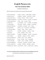
complete the sentences intermediate level 5
... English Banana.com Test Your Reading Skills Complete the Sentences – Intermediate Level Answers: b) born c) stand d) colour c) chip b) surprise a) buskers b) it
Ngày tải lên: 25/08/2016, 17:35

complete the sentences intermediate level 6
... English Banana.com Test Your Reading Skills Complete the Sentences – Intermediate Level Answers: b) comes d) cars a) broadcasting c) tackle c) shivering a) four
Ngày tải lên: 25/08/2016, 17:35

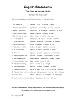
complete the sentences intermediate level 7
... English Banana.com Test Your Reading Skills Complete the Sentences – Intermediate Level Answers: c) out b) walking d) their a) can’t c) too d) advertise c) booked b) all c) place
Ngày tải lên: 25/08/2016, 17:35

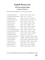
complete the sentences intermediate level 8
... English Banana.com Test Your Reading Skills Complete the Sentences – Intermediate Level Answers: c) enough d) dog c) Donald b) photos c) sofa c) many b) start
Ngày tải lên: 25/08/2016, 17:35

complete the sentences intermediate level 9
... English Banana.com Test Your Reading Skills Complete the Sentences – Intermediate Level Answers: a) recharge b) skin c) of a) for a) improvement b) to d) yet c)
Ngày tải lên: 25/08/2016, 17:36

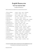
complete the sentences intermediate level 1
... Test Your Reading Skills Complete the Sentences – Intermediate Level Answers: d) pound c) hairdresser’s c) coffee a) ten d) resigned b) painting b) on c) up a) socks 10 c) fishing For more fun
Ngày tải lên: 25/08/2016, 17:36

complete the sentences intermediate level 2
... English Banana.com Test Your Reading Skills Complete the Sentences – Intermediate Level Answers: b) at d) freezer a) Wednesday c) open c) beautiful d) passionate
Ngày tải lên: 25/08/2016, 17:37


Tài liệu THE DIGITAL LOGIC LEVEL-3 ppt
... programmable logic array The little squares represent fuses that can be burned out to determine the function to be computed The fuses are arranged in two matrices: the upper one for the AND gates and the ... Figure 3-2 The symbols and functional behavior for the five basic gates A B C A B C A A B ABC ABC A 0 0 1 1 B 0 1 0 1 C 1 1 (a) M 0 1 1 B ABC C C ABC (b) Figure 3-3 (a)...
Ngày tải lên: 12/12/2013, 09:15
- developing skills for the toeic test level 3
- complete the sentences with the correct form of the verbs
- complete the sentences with the correct prepositions
- complete the sentences for each situation using v ing
- complete the sentences for each situation using to infinitive
- complete the sentences using the one of the following adj