Mechanical Movement Episode 2 doc


Friction and Lubrication in Mechanical Design Episode 2 Part 1 docx
... (N/m2) x 106 (N/m2) 1 2 3 4 5 6 7 8 9 10 11 12 13 0. 025 1 0.0361 0. 025 1 0.036 1 0. 025 1 0.036 1 0 .2 198 0 .2 198 0 .2 198 0.031 I 0.031 1 0 .26 49 0 .26 49 3. 72 ... 34-44. Vol. 199(C2), pp. 95-1 02. Vol. 199(C2), pp. 103-1 11. 29 8-307. Vol. 2, pp. 52- 58. 1968, pp. 23 3 -23 9. Design of Fluid Film Bearings 24 7 6. 7. 8. 9. 1...
Ngày tải lên: 05/08/2014, 09:20

Friction and Lubrication in Mechanical Design Episode 2 Part 2 docx
... Steel Copper 0. 42 0.38 0.17 0 .20 Table 7 .2 Material Properties Steel 43 7800 473 20 3.4 Copper 40 1 8930 386 103 Chromium 94 7135 450 25 0 Tin 67 728 0 22 2 46 10W30 0.145 888 ... = rolling speed = UI + U2 L U,, U2 = rolling speeds of rollers 1, 2 RI R2 RI +R2 R = effective radius = - RI, R2 = radii of rollers 1, 2 1 E’ = effect...
Ngày tải lên: 05/08/2014, 09:20

Friction and Lubrication in Mechanical Design Episode 2 Part 2 doc
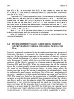
... Steel Copper 0. 42 0.38 0.17 0 .20 Table 7 .2 Material Properties Steel 43 7800 473 20 3.4 Copper 40 1 8930 386 103 Chromium 94 7135 450 25 0 Tin 67 728 0 22 2 46 10W30 0.145 888 ... Sheu [25 ]: 1 I + 0 .24 1[(1 + 14.8 z0.83)80.64] &= (7 .28 ) 27 2 Chapter 7 and its location z* is calculated from: where a' = 0 .21 9(1 - e-1fi6.368)...
Ngày tải lên: 05/08/2014, 09:20

Friction and Lubrication in Mechanical Design Episode 2 Part 3 docx
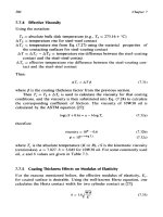
... and K2, c2, p2, E2 in Eqs. (7 .27 ) and (7 .28 ), where f is replaced byf,, L is replaced by L = 32J'm. 2. U1 + U2 3. Mean rolling velocity U = - 2 rl r2 Effective ... = 27 3.16 + "C, ml and m2 are kinematic viscosity in centi- &I* cc19 Pcl9 &I* K2 9 c2 * P2 * E2 are replaced by Kc2 * cc2 * Pc2 , Ec2 * D = 01. D =...
Ngày tải lên: 05/08/2014, 09:20

Friction and Lubrication in Mechanical Design Episode 2 Part 5 doc
... the centrifugal Wear 33 7 13. 14. 15. 16. 17. 18. 19. 20 . 21 . 22 . 23 . 24 . 25 . 26 . 27 . 28 . 29 . 30. 31. 32. 33. 34. Blok, H., “Les Temperatures de Surfaces dan les Conditions ... Chapter 9 MAXIMUM ALLOWABLE 20 0 SINK TEMPERATURE 4oo 120 0 - f 1400- 1600- v) 1800- W a 5 20 00- w (3 22 00 - 24 00 - 26 00 - 28 00 - 3000 Figure 9...
Ngày tải lên: 05/08/2014, 09:20

Friction and Lubrication in Mechanical Design Episode 2 Part 6 doc
... (4.99 922 8 cm) (2. 6 924 cm) (9.44 62 cm) (6.5171 32 cm) (6.51 1798 cm) (6.50478 cm) (1.464564 cm) (1.67386 cm) (0.436 626 cm) (0.005334 cm) (0.009653 cm) Load Figure 9.1 2 Diagrammatic ... Load condition (2) = 0 .25 (2) = 0.50 (2) = 0.75 I. Uniform thickness and external loading 73,456.4 70,378.9 50,506.1 2. Uniform thickness and internal loa...
Ngày tải lên: 05/08/2014, 09:20

Friction and Lubrication in Mechanical Design Episode 2 Part 8 docx
... Nitrogen,” J. Appl. Mech., 1954, Vol. 21 , p. 395. 183, pp. 723 - 729 . pp. 20 3 -22 4. 1949, Vol. 71, pp. 25 9 -26 8. pp. 22 2 -23 5. 74, pp. 22 9 -24 5. Case Illustrations of Surface Damage ... at 925 °C. A 3000 A LPCVD silicon nitride was deposited on the thermal oxide. The Case Illustrations of Surface Damage 405 17. 18. 19. 20 . 21 . 22 . 23 . 2...
Ngày tải lên: 05/08/2014, 09:20