Mechanics of Materials 1 Part 14 pdf
Mechanics of Materials 1 Part 14 pdf
... L 1. 0 0 005 010 015 Ox) 025 0 r/d 0 Fig. 10 .23. Stress concentration factor K, for a round tension bar with a U groove. 450 Mechanics of Materials 2 $11 .1 10 2 lo4 10 6 ... (19 30), 212 . Delft, April, 19 65. Wear (19 66), 9,4 -19 . Trans ASME (19 53), 75,327. Proc. I Mech. E. (19 39), 14 1, 223. to some contact stress problems”, J. Ap...
Ngày tải lên: 10/08/2014, 12:21

High Cycle Fatigue: A Mechanics of Materials Perspective part 4 pdf
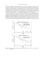
... conservative nature of this design Applied Stress Number of Cycles to Crack Initiation Average Design Allowable Distribution Of Lives Figure 1. 2. Schematic of S–N curve with illustration of scatter. Introduction ... treated with enough of a factor of safety (or uncertainty) to account for a worst case scenario in terms of material capability. The shape of the S–N curves d...
Ngày tải lên: 03/07/2014, 20:20

High Cycle Fatigue: A Mechanics of Materials Perspective part 6 pdf
... = 1 10 7 A B C Figure 2 .11 . Schematic of S–N curves obtained at constant values of R. Alternating stress R = 0 R = 0.7 R = 1 A B C N = 10 7 N = 10 4 Mean stress Figure 2 .12 . Schematic of ... 8. 0 500 10 00 15 00 2000 10 3 10 4 10 5 10 6 10 7 10 8 Failure Run-out Stress amplitude (MPa) Cycles to failure σ m = –784 MPa σ m = +784 MPa σ m = 0 MPa Figure 2 .16...
Ngày tải lên: 03/07/2014, 20:20
High Cycle Fatigue: A Mechanics of Materials Perspective part 14 docx
... and 60 70 80 90 10 0 11 0 12 0 13 0 10 4 10 5 10 6 10 7 10 8 S –N tests S –N run-out Step run-out Step tests σ max (ksi) N Ti -17 R = 0 .1 350 Hz Figure 3.39. Fatigue data for Ti -17 at R =0 1. Accelerated ... fits for Ti-6Al-4V. 12 2 Introduction and Background 50 60 70 80 90 10 0 10 4 10 5 10 6 10 7 10 8 10 9 S –N tests S –N run-out Step run-out Step tests σ...
Ngày tải lên: 03/07/2014, 20:20

High Cycle Fatigue: A Mechanics of Materials Perspective part 16 pdf
... of these subjects are discussed here in Part Two of this book. Accelerated Test Techniques 13 9 11 . Forsyth, P.J.E., The Physical Basis of Metal Fatigue, Blackie & Son Ltd, London, 19 69. 12 . ... Mechanical Behaviour of Materials, ICM-8, F. Ellyin, and J.W. Provan, eds Vol. III, 19 99, pp. 11 61 11 66. 22. Maxwell, D.C. and Nicholas, T., “A Rapid Method for Generation...
Ngày tải lên: 03/07/2014, 20:20
High Cycle Fatigue: A Mechanics of Materials Perspective part 23 pdf
... HCF 1k 2 613 654 2 613 654 6370632 8805680 10 000 0.5/1k 16 400000 1 640 613 8805680 10 000 0.5/1k 71 682975 7 16 8 613 8 80 56 80 10 0000 0.5/1k 14 298296 14 2 63 8 80 56 80 10 0000 0.5/1k ... 10 0000 0.5/1k 9 312 872 93 63 8 80 56 80 10 0000 0.5/1k 405933382 4059 63 8807280 10 000 0.5/1k 14 2 814 527 14 2 81 16222 8806580 10 000 0.5/1k 94 1...
Ngày tải lên: 03/07/2014, 20:20

High Cycle Fatigue: A Mechanics of Materials Perspective part 40 pdf
... Considerations 383 0 2 4 6 8 10 12 10 4 10 5 10 6 10 7 10 8 10 9 Model sqrt Experiment sqrt Model parameter N model 25% variation Figure 8.4. Representation of model using square root of stress with 25% ... based on a parameter 0 20 40 60 80 10 0 10 4 10 5 10 6 10 7 10 8 10 9 Model linear Experiment linear Model parameter N model 25% variation Figure 8.3. Repre...
Ngày tải lên: 03/07/2014, 21:20

High Cycle Fatigue: A Mechanics of Materials Perspective part 42 pdf
... approach, particularly with respect to obtaining useful crack growth thresholds for use in engineering design. HCF Design Considerations 405 0 200 400 600 800 10 00 10 4 10 5 10 6 10 7 R = 1 R = 0 .1 R ... 0.9 Figure 8 .18 . Damage tolerant Haigh diagram: K th constant for R>07. 0 50 10 0 15 0 200 250 0 200 400 600 800 10 00 12 00 Goodman a initial = 0.05 mm a initial...
Ngày tải lên: 03/07/2014, 21:20

High Cycle Fatigue: A Mechanics of Materials Perspective part 44 pdf
... confusion to the representation of threshold data, often 422 Applications 0 1 2 3 4 5 0 0.2 0.4 0.6 0.8 1 K max R A B Figure 8. 41. Schematic of two-parameter threshold in plot of K max versus R. So, when ... represented and some of the interpretations of the meaning of the shape of the various plots. A review of some of the key considerations that have evolved over many...
Ngày tải lên: 03/07/2014, 21:20

High Cycle Fatigue: A Mechanics of Materials Perspective part 47 pdf
... Applications 10 10 10 –9 10 –8 10 –7 10 –6 10 –5 11 0 10 0 ΔK applied ΔK effective da/dN (m/cycles) Baseline R = 0 .1 Ti-6Al-4V R = 0 .1 ΔK (MPa√m) Figure 8.65. The FCGR data for LSP samples at R =0 1 as ... = √ afa/W (8 .12 ) fa/W = 1 12 15−50402a/W +14 4979a/W 2 −220 211 a/W 3 +12 9270a/W 4 1 a/W 3/2 (8 .13 ) where a is the crack length measured...
Ngày tải lên: 03/07/2014, 21:20
- thiết kế bài giảng vật lý 10 tập 1 part 4 pdf
- fce use of english 1 student book pdf
- fce use of english 1 express publishing pdf
- official ielts practice materials 1 free download pdf
- the lord of the rings part 2 pdf free download
- cpe use of english 1 virginia evans pdf
- thiết kế bài giảng ngữ văn 12 nâng cao tập 1 part 5 pdf
- tự học ngôn ngữ lập trình java tập 1 part 2 pdf
- handbook of shaft alignment part 13 pdf