Gear Geometry and Applied Theory Episode 3 Part 3 ppsx

Gear Geometry and Applied Theory Episode 2 Part 3 pot
... GDZ CB672- 13 CB672/Litvin CB672/Litvin-v2.cls February 27, 2004 0 :36 13. 6 Internal Pin Gearing 36 5 Figure 13. 5.6: Rack-cutter tooth profile. 13. 6 INTERNAL PIN GEARING Internal pin gearing is applied ... Y 1 =−r 1 cos φ 1 . ( 13. 5 .3) P1: GDZ/SPH P2: GDZ CB672- 13 CB672/Litvin CB672/Litvin-v2.cls February 27, 2004 0 :36 35 8 Cycloidal Gearing Figure 13. 4 .3: Lines of action of...
Ngày tải lên: 08/08/2014, 12:21

Gear Geometry and Applied Theory Episode 2 Part 6 ppsx
... 3D-space. A gear drive formed by a helical gear and a worm gear is a particular case of a gear drive with crossed axes (Figure 16.1.2). Gear tooth surfaces are in line contact for involute helical gear ... canonical design discussed for nonstandard gears can be applied as well for the design of standard crossed helical gears. Due to errors of crossing angle γ o and shortest...
Ngày tải lên: 08/08/2014, 12:21
Gear Geometry and Applied Theory Episode 1 Part 9 pot
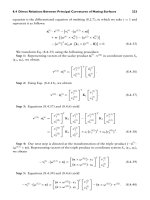
... η 1 = −a 31 v (12) q + a 33 + a 31 v (12) s tan η 2 a 33 + a 32 v (12) q − v (12) s tan η 2 (9 .3. 4) v (1) s = a 33 a 13 + a 23 tan η 1 (9 .3. 5) v (1) q = a 33 tan η 1 a 13 + a 23 tan η 1 . (9 .3. 6) P1: GDZ/SPH ... κ q )a 33 (8.4.49) κ f − κ h = 2a 13 a 23 a 33 sin 2σ = a 2 23 − a 2 13 + (κ s − κ q )a 33 a 33 cos 2σ (8.4.50) κ f + κ h = (κ s +...
Ngày tải lên: 08/08/2014, 12:21
Gear Geometry and Applied Theory Episode 1 Part 10 pps
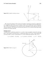
... )(θ = tan α − α) was proposed by Cheng [1992]: α = (3 ) 1 /3 − 2 5 θ + 9 175 3 2 /3 θ 5 /3 − 2 175 3 1 /3 θ 7 /3 +··· for θ<1.8 (10.2.10) Extended and Shortened Involute Curves These curves are traced ... (9.4 .33 ) cos(θ 1 − φ 1 ) − cos(θ 2 + φ 2 ) = 0 (9.4 .34 ) sin(θ 1 − φ 1 ) − sin(θ 2 + φ 2 ) = 0. (9.4 .35 ) Step 5: Analyzing Eqs. (9.4 .34 ) and (9.4 .35 ), we obtain θ 1...
Ngày tải lên: 08/08/2014, 12:21
Gear Geometry and Applied Theory Episode 2 Part 1 pot
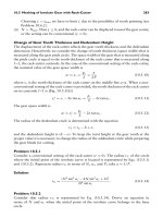
... rack-cutter and the pinion and gear. Points M 1 and M 2 , and N 1 and N 2 , respectively, are the points of tangency of the rack-cutter with the pinion and the gear. However, the pinion and gear tooth ... h o , and generally the tooth height of nonstandard gears is less than the tooth height of standard gears. However, the tooth height of nonstandard gears is the same as t...
Ngày tải lên: 08/08/2014, 12:21

Gear Geometry and Applied Theory Episode 2 Part 2 doc
... 27, 2004 0 :32 33 4 Noncircular Gears Figure 12.8.1: Combined gear mechanism with identical centrodes for (i) gears 1 and 3, and (ii) gears 2 and 4. Because the above identity of gear centrodes ... CB672/Litvin-v2.cls February 27, 2004 0 :32 33 6 Noncircular Gears 1 2 3 4 Figure 12.9.1: Generation of noncircular gears by application of the noncircular master -gear and the ra...
Ngày tải lên: 08/08/2014, 12:21

Gear Geometry and Applied Theory Episode 2 Part 4 pdf
... (u,φ, and m): a 11 u + a 13 m = b 1 a 21 u + a 22 φ + a 23 m = b 2 a 31 u + a 32 φ + a 33 m = b 3 . (14.4.14) P1: GDZ/SPH P2: GDZ CB672-14 CB672/Litvin CB672/Litvin-v2.cls February 27, 2004 0 :39 39 4 ... driving gear 1 and driven gear 2, in coordinate systems S 1 and S 2 , respectively. A right-hand helical gear 1 is shown in Fig. 14 .3. 1. Figure 14 .3. 2 shows the...
Ngày tải lên: 08/08/2014, 12:21

Gear Geometry and Applied Theory Episode 2 Part 5 pptx
... base circle of gear 1 (Fig. 14 .3. 2) θ, θ 1 , and θ 2 surface parameter of the screw involute surface (Figs. 14 .3. 2 and 14 .3. 3) φ, φ 1 , and φ 2 angle of gear rotation (Figs. 14.4.1 and 14.5.1) η 2 half ... of center distance is applied and (b) when an error E = 1mmis applied; (c) path of contact on gear surface when no error is applied and (d) when an error E =...
Ngày tải lên: 08/08/2014, 12:21
Gear Geometry and Applied Theory Episode 2 Part 7 pps
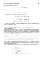
... Novikov–Wildhaber helical gears and modified involute helical gears. 17.4 PROFILE-CROWNED PINION AND GEAR TOOTH SURFACES The profile-crowned pinion and gear tooth surfaces are designated as σ and 2 , re- spectively, ... Pressure -8.180e+01 +2.500e+01 +9. 731 e+01 +1.696e+02 +2.419e+02 +3. 142e+02 +3. 865e+02 +4.588e+02 +5 .31 1e+02 +6. 035 e+02 +6.758e+02 +7.481e+02 +8.204e+02...
Ngày tải lên: 08/08/2014, 12:21
Gear Geometry and Applied Theory Episode 2 Part 8 pps
... 509 Figure 18.1.1: Face -gear drive in 3D-space. Rotor shaft output Sun gear NOTAR TM output Combining gear Driving spur pinion Engine input Face-gears Figure 18.1.2: Application of face -gear drive in helicopter ... 18.4 .3( a) and 18.4 .3( b)]. The contact lines correspond to the meshing of the shaper with face -gear 2 and pinion 1, respectively. The current instantaneous point o...
Ngày tải lên: 08/08/2014, 12:21