Classical Mechanics - 3rd ed - Goldstein, Poole & Safk Episode 1 Part 3 ppsx

Mechanical Devices Sourcebook 3rd ed mcgraw hil 2001 Episode 2 Part 3 pdf
... of the han- dle and retention cams as the box is moved rearward and downward. Sclater Chapter 12 5 /3/ 01 1:24 PM Page 409 415 Sclater Chapter 12 5 /3/ 01 1:25 PM Page 415 428 PROBE-AND-SOCKET FASTENERS ... Chapter 12 5 /3/ 01 1:25 PM Page 419 4 13 From Handbook of Fastening and Joining of Metal Parts, McGraw-Hill, Inc. (A) A method for fastening capacitor plates to a structure wi...
Ngày tải lên: 05/08/2014, 12:20

Brownstein S., et al. Barron''''s GRE.12th.ed.(Barrons)(669s)(1997) Episode 1 Part 8 ppsx
Ngày tải lên: 22/07/2014, 02:20

Brownstein S., et al. Barron''''s GRE.12th.ed.(Barrons)(669s)(1997) Episode 1 Part 3 pdf
Ngày tải lên: 22/07/2014, 02:20

Dimensioning and Tolerancing Handbook Episode 1 Part 3 ppsx
... designer’s expectations. Fig. 3- 2 e shows a combination of Figs. 3- 2 b and 3- 2 c (like Figs. 3 -1 b and 3 -1 c), in that it allows the shape to be small at one end and large at the other. Unlike Figs. 3 -1 b and 3 -1 c, Fig. 3- 2 e ... including Y14 Main Committee, Y14 .3 Multiview and Sectional View Drawings, Y14.5 Dimensioning and Tolerancing, Y14 .11 Molded Part Drawings...
Ngày tải lên: 21/07/2014, 15:20

Process Selection - From Design to Manufacture Episode 1 Part 3 ppsx
... [A10] [F1] [F 13] [A9] [F14] [F12][F 13] [F12][F 13] [F15][F17] [F 21] [F15][F17] [F18[F 21] [F15][F17] [F18[F 21] [W12][F2] [F10][F14] [A4] [W12][F2] [F2] [F 13] [A9] [F14] [F 13] [F16][F 21] [F16][F 21] [F 21] [W12][F1] [F5][F6][F8] [F10][A1] [A2][A4] [A5][A10] [W12][F1] [F10][A4] [A10] [F1] [A9][F 13] [F14] [F12][F 13] ... [W1] [S1][S6][S8] [W1][W2] [W3][W9] [W 11] [W 13] [W14] [B1...
Ngày tải lên: 21/07/2014, 16:21
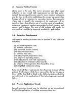
Advanced Welding Processes Episode 1 Part 3 ppsx
... y0 w0 h1" alt=""
Ngày tải lên: 21/07/2014, 17:20

Longman Toeic Intermediate Episode 1 Part 3 ppsx
... src="data:image/png;base64,iVBORw0KGgoAAAANSUhEUgAABKcAAAaTCAIAAAC3lti4AAAACXBIWXMAABYlAAAWJQFJUiTwAAAgAElEQVR42uzdsU7bXBiAYRusoIIEd1UYKAiJIXfADXhhOjoTiy+kqqqKdqIVlcqS+wGJJcv5B6T+FYQACXHs4+eZqAkp+SxVffmCXaaUCgAAADK1YQQAAACqDwAAANUHAACA6gMAAED1AQAAoPoAAABQfQAAAKoPAAAA1QcAAIDqAwAAQPUBAACg+gAAAFB9AAAAqD4AAADVBwAAgOoDAABA9QEAAKD6AAAAUH0AAACoPgAAAFQfAACA6gMAAED1AQAAoPoAAABQfQAAAKg+AAAAVB8AAACqDwAA...
Ngày tải lên: 21/07/2014, 21:21

342 TOEIC Vocabulary Tests Episode 1 part 3 ppsx
... tentative (d) evasive Q2 adj. distorted; crooked; twisted; askew (a) valid (b) town (c) previous (d) wry Q3 adj. sticking together; forming a unit or union; united; related to each other (a) grateful ... (b) copy (c) present (d) drive 10 0 Answers Index PHOTOCOPIABLE © www.english-test.net Test 63 TOEIC Vocabulary / Word by Meaning / Test # 63 Q1 adj. somewhat (a) part (b) inclusive (c)...
Ngày tải lên: 21/07/2014, 22:20
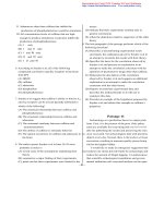
GMAT reading Episode 1 Part 3 ppsx
... been located, and migrated to northern (5) states, with the largest number moving, it is claimed, between 19 16 and 19 18. It has been frequently assumed, but not proved, that the majority of ... Passage 12 Federal efforts to aid minority businesses began in the 19 60’s when the Small Business Administration (SBA) began making federally guaranteed loans and govern- ment-sponso...
Ngày tải lên: 22/07/2014, 02:20