Engineering Analysis with Ansys Software Episode 1 Part 6 ppsx

Engineering Analysis with Ansys Software Episode 1 Part 1 potx
... (1. 12) 1 0 w i Rdx = 1 0 1 − −A 1 x 2 +(A 1 1) x +2A 1 dx = 13 6 A 1 − 1 2 = 0 (1. 13) Consequently, the first-order approximate solution is obtained as ¯u 1 (x) = x + 3 13 x(x 1) (1. 14)
Ngày tải lên: 06/08/2014, 11:21

Engineering Analysis with Ansys Software Episode 1 Part 3 ppt
... c 3 1 c 1 1 b 1 1 c 2 1 b 2 1 c 3 1 b 3 1 ⎤ ⎥ ⎦ = 1 2 (1) ⎡ ⎢ ⎣ y 2 1 −y 3 1 0 y 3 1 −y 1 1 0 y 1 1 −y 2 1 0 0 x 3 1 −x 2 1 0 x 1 1 −x 3 1 0 x 2 1 −x 1 1 x 3 1 −x 2 1 y 2 1 −y 3 1 x 1 1 −x 3 1 y 3 1 −y 1 1 x 2 1 −x 1 1 y 1 1 −y 2 1 ⎤ ⎥ ⎦ (1. 102) Since ... Element 1. From Equations (1. 73) and (1. 69a)...
Ngày tải lên: 06/08/2014, 11:21

Engineering Analysis with Ansys Software Episode 1 Part 4 docx
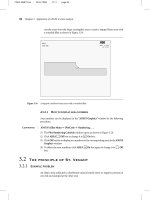
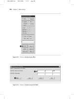
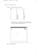
... and displayed on the ANSYS Graphics” window. Ch02-H6875.tex 24 /11 /2006 17 : 2 page 49 2 .4 Solution stage 49 A Figure 2 . 14 Type of analysis definition. Select the type of analysis that is appropriate ... beam on the ANSYS Graphics window as shown in Figure 3.7. Ch02-H6875.tex 24 /11 /2006 17 : 2 page 46 46 Chapter 2 Overview of ANSYS structure and visual capabilities...
Ngày tải lên: 06/08/2014, 11:21

Engineering Analysis with Ansys Software Episode 1 Part 5 pot
... Ch03-H68 75. tex 24 /11 /2006 17 : 2 page 78 78 Chapter 3 Application of ANSYS to stress analysis 50 mm 50 N 10 mm DOF X Figure P3.4 A half model of the beam in Problem 3.2. 50 mm 50 N 10 mm 10 mm Figure ... sense. 20 30 40 50 60 Ϫ300 Ϫ200 10 0 0 10 0 200 300 x-coordinate, x (mm) Longitudinal stress, σ, (MPa) 10 0 N 15 0 N Pϭ200 N 200 N 15 0 N P 10 0 N ANSYS Experiment T...
Ngày tải lên: 06/08/2014, 11:21
Engineering Analysis with Ansys Software Episode 1 Part 6 ppsx
... →Areas →Free (1) The Mesh Areas window opens. Ch03-H6875.tex 24 /11 /20 06 17 : 2 page 93 3.3 Stress concentration due to elliptic holes 93 0 5 10 0 5 10 15 20 x (mm) 200 19 0 18 0 10 0 Longitudinal ... in Figure 3 .62 . 3.2.3.5 SOLUTION PROCEDURES Command ANSYS Main Menu →Solution →Solve →Current LS Ch03-H6875.tex 24 /11 /20 06 17 : 2 page 86 86 Chapter 3 Application of A...
Ngày tải lên: 06/08/2014, 11:21

Engineering Analysis with Ansys Software Episode 1 Part 7 potx
... (3 .11 ) 0 .1 1.0060 1. 0062 1. 0048 1. 0060 0.2 1. 0246 1. 0254 1. 0208 1. 0245 0.3 1. 0 577 1. 0594 1. 0 510 1. 0 574 0.4 1. 1094 1. 111 8 1. 1000 1. 1090 0.5 1. 18 67 1. 1892 1. 175 7 1. 1862 0.6 1. 3033 1. 3043 1. 29 21 1.30 27 0 .7 ... 1. 1892 1. 175 7 1. 1862 0.6 1. 3033 1. 3043 1. 29 21 1.30 27 0 .7 1. 4882 1. 48 41 1. 477 9 1. 4 873 0.8 1. 81...
Ngày tải lên: 06/08/2014, 11:21

Engineering Analysis with Ansys Software Episode 1 Part 8 pps
... k b 2 −x 2 (P3 .17 a) k = 2P’ πb 2 (P3 .17 b) b = 2 √ π P’R 1 R 2 R 1 +R 2 1 −ν 2 1 E 1 + 1 −ν 2 2 E 2 (P3 .17 c) p 0 = 1 √ π P’(R 1 +R 2 ) R 1 R 2 · 1 1 ν 2 1 E 1 + 1 ν 2 2 E 2 (P3 .17 d) PROBLEM ... are attached: Command ANSYS Utility Menu →Select →Entities … Ch03-H 687 5.tex 24 /11 /2006 17 : 2 page 14 0 14 0 Chapter 3 Application of ANS...
Ngày tải lên: 06/08/2014, 11:21
Engineering Analysis with Ansys Software Episode 1 Part 9 pdf
... to step 2 (Figure 4 .15 ). Ch04-H6875.tex 24 /11 /2006 17 : 47 page 15 1 4.2 Mode analysis of a straight bar 15 1 F G Figure 4 .14 Window of Density for Material Number 1. A B C Figure 4 .15 Window of Create ... button. Ch04-H6875.tex 24 /11 /2006 17 : 47 page 15 9 4.2 Mode analysis of a straight bar 15 9 (2) Then, the window Subspace Modal Analysis, as shown in Figure 4. 2...
Ngày tải lên: 06/08/2014, 11:21
Engineering Analysis with Ansys Software Episode 1 Part 10 potx
... 8.3e−3 1. 4e−3 7 8.3e−3 2 .15 e−3 8 0 0.6e−3 9 8.3e−3 −0.8e−3 10 10 .5e−3 −0.8e−3 11 10 .5e−3 0.8e−3 12 8.3e−3 0.8e−3 13 0 −0.6e−3 0.3e−3 14 8.3e−3 −2 .15 e−3 0.3e−3 15 8.3e−3 2 .15 e−3 0.3e−3 16 0 0.6e−3 ... Ch04-H6875.tex 24 /11 /2006 17 : 47 page 17 6 17 6 Chapter 4 Mode analysis D C Figure 4.57 ANSYS Graphics window. Figure 4.58 ANSYS Graphics window. Ch04-H6875.tex...
Ngày tải lên: 06/08/2014, 11:21
Engineering Analysis with Ansys Software Episode 2 Part 1 potx
... 0 0.05 5 0.005 0. 01 6 0.035 0. 01 7 0.035 0.045 8 0.005 0.045 9 0.005 0. 015 10 0. 013 0. 015 11 0. 013 0. 02 12 0.005 0. 02 13 0. 023 0. 01 14 0.0 32 0. 01 15 0.0 32 0. 02 16 0. 023 0. 02 (2) In the same window, ... Radius 1 0 0.0 12 2 2 0.005 0.0 12 2 3 0.035 0.0 12 2 4 0.04 0.0 12 2 5 0 0.0 428 0.0 022 6 0.005 0.0 428 7 0.035 0.0 428 8 0.04 0.0 428 9 0.00 72 0....
Ngày tải lên: 06/08/2014, 11:21
Engineering Analysis with Ansys Software Episode 2 Part 2 ppt
... Graphics window. Ch05-H6875.tex 24 /11 /20 06 17: 8 page 22 2 22 2 Chapter 5 Analysis for fluid dynamics Table 5 .2 Keypoint numbers for making areas Area No. KPs 1 1 ,2, 3,4 2 2,5,6,3 3 5,7,8,6 A Figure 5.11 ... Ch05-H6875.tex 24 /11 /20 06 17: 8 page 22 1 5 .2 Analysis of flow structure in a diffuser 22 1 Figure 5.9 ANSYS Graphics window. B A Figure 5.10 Window of Create Area...
Ngày tải lên: 06/08/2014, 11:21

Engineering Analysis with Ansys Software Episode 2 Part 3 pot
... 24 /11 /20 06 17: 8 page 23 8 23 8 Chapter 5 Analysis for fluid dynamics B C Figure 5 .34 ANSYS Graphics window. E F G Figure 5 .35 Window of By Nodes. Ch05-H6875.tex 24 /11 /20 06 17: 8 page 24 1 5 .2 Analysis ... SPACE 115 2 50 0 .2 31 5– 4505 530 – 6 50 0 .2 730 – 8405 9 50 0 .2 10 40 0 .2 A Figure 5.16 Window of Mesh Areas. B Figure 5.17 ANSYS Graphics window. Ch05...
Ngày tải lên: 06/08/2014, 11:21
Engineering Analysis with Ansys Software Episode 2 Part 4 pps
... Y 10 0 20 −0.03 3 0 .2 −0.03 4 0 .2 0 5 0 .2 0.03 6 0 0.03 7 0.05587 −0. 026 48 8 0.0716 0 9 0.08587 0. 025 48 10 0.0 841 3 0. 026 48 11 0.06885 0 12 0.0 541 3 −0. 025 48 (3) After finishing step (2) , 12 keypoints ... click [B] OK. (2) The calculated result for velocity vectors appears on ANSYS Graphics window as shown in Figure 5.59. Ch05-H6875.tex 24 /11 /20 06 17: 8 p...
Ngày tải lên: 06/08/2014, 11:21
Engineering Analysis with Ansys Software Episode 2 Part 6 pptx
... Nodes. A B Figure 6. 68 Select All Nodes. Ch 06- H6875.tex 24 /11 /20 06 17: 48 page 29 9 6. 3 Steady-state thermal analysis of a pipe intersection 29 9 A Figure 6. 62 New Analysis window. A Figure 6. 63 Analysis ... temperature Temperature [ ◦ C] 21 93 149 20 4 26 0 Convection coefficient 41.918 39.8 52 34 .63 7 27 . 06 21 .7 46 [W/m 2 ◦ C] Density [kg/m 3 ] 7889 788...
Ngày tải lên: 06/08/2014, 11:21
- thiết kế bài giảng lịch sử 8 tập 1 part 6 docx
- thiết kế bài giảng vật lý 10 tập 1 part 6 potx
- thiết kế bài giảng sinh học 11 nâng cao tập 1 part 6 pps
- tiếng nhật dành cho người mới bắt đầu tập 1 part 6 pdf
- tự học tiếng pháp tập 1 part 6 pdf
- tư vấn quản lý tập 1 part 6 pdf
- vol 1 part 6 chap 35
- vol 1 part 6 chap 36
- vol 1 part 6 chap 37