Mechanical Science HandbooksMechanical Science Handbooks 10000 Part 2 pot

Mechanical Science HandbooksMechanical Science Handbooks 10000 Part 2 pot
... (Cont.) Figure 22 2- Stroke Intake 26 Figure 23 2- Stroke Compression 27 Figure 24 2- Stroke Fuel Injection 27 Figure 25 2- Stroke Power 27 Figure 26 Fuel Injector Cutaway 31 Figure 27 Fuel Injector ... Engine Fundamentals Intentionally Left Blank ME-01 Rev. 0 Page viii Department of Energy Fundamentals Handbook MECHANICAL SCIENCE Module 1 Diesel Engine Fundamentals Die...
Ngày tải lên: 21/07/2014, 17:20
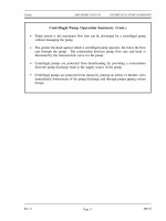
Mechanical Science HandbooksMechanical Science Handbooks 10000 Part 12 pot
... 12. Check valves in the suction and discharge ports allow flow in only one direction. During the suction stroke, the piston moves to the left, causing the check valve in the suction Figure 12 ... the suction and discharge nozzles. An example of a diaphragm pump is shown in Figure 20 . ME-03 Rev. 0 Page 26 Pumps DOE-HDBK-1018/1-93 POSITIVE DISPLACEMENT PUMPS With the large number of teeth...
Ngày tải lên: 21/07/2014, 17:20

Mechanical Science HandbooksMechanical Science Handbooks 20000 Part 2 pps
... DOE-HDBK-1018 /2- 93 Valves TABLE OF CONTENTS (Cont.) Manually Operated Plug Valve Installation 24 Plug Valve Glands 24 Diaphragm Valves 24 Diaphragm Construction 25 Diaphragm Valve Stem Assemblies 27 Diaphragm ... DOE-HDBK-1018 /2- 93 Valves LIST OF FIGURES (Cont.) Figure 21 Bar-Stock Instrument Valve 34 Figure 22 Swing Check Valve 35 Figure 23 Operation of Tilting Disk Check Va...
Ngày tải lên: 21/07/2014, 17:20
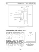
Mechanical Science HandbooksMechanical Science Handbooks 10000 Part 13 pps
... overpressurization by a relief valve on the upstream side of the pump discharge valve. ME-03 Rev. 0 Page 28
Ngày tải lên: 21/07/2014, 17:20
Mechanical Science HandbooksMechanical Science Handbooks 10000 Part 11 doc
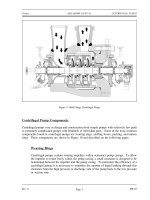
... DOE-HDBK-1018/1-93 Pumps Mechanical Seals In some situations, packing material is not adequate for sealing the shaft. One common alternative method for sealing the shaft is with mechanical seals. Mechanical ... in design and construction from simple pumps with relatively few parts to extremely complicated pumps with hundreds of individual parts. Some of the most common components found...
Ngày tải lên: 21/07/2014, 17:20

Mechanical Science HandbooksMechanical Science Handbooks 10000 Part 10 docx
... pump 2. 3 EXPLAIN the importance of viscosity as it relates to the operation of a reciprocating positive displacement pump. 2. 4 DESCRIBE the characteristic curve for a positive displacement pump. 2. 5 ... Pumps TERMINAL OBJECTIVE 2. 0 Without references, DESCRIBE the purpose, construction, and principle of operation for positive displacement pumps. ENABLING OBJECTIVES 2. 1 STATE the dif...
Ngày tải lên: 21/07/2014, 17:20

Mechanical Science HandbooksMechanical Science Handbooks 10000 Part 9 pptx
... 22 Diaphragm Pumps 26 Positive Displacement Pump Characteristic Curves 27 Positive Displacement Pump Protection 28 Summary 28 Rev. 0 ME-03 Page i Department of Energy Fundamentals Handbook MECHANICAL ... at a pressure between 20 0 psi and 300 psi as the high pressure fluid enables a single- stage air ejector to draw a vacuum of about 26 inches Hg. Figure 10 Jet Pump ME- 02 Rev...
Ngày tải lên: 21/07/2014, 17:20
Mechanical Science HandbooksMechanical Science Handbooks 10000 Part 8 doc
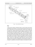
... temperature T 1in = 20 0°F T 1out = 145°F U o = 70 BTU/hr-ft 2 -°F A o = 75ft 2 T 2 = represents the cold fluid temperature T 2in =80°F T 2out = 120 °F Counter flow ∆T lm = (20 0 120 o F) (145 80 o F) ln (20 0 ... Heat Exchangers ME- 02 Rev. 0 Page 10 TYPES OF HEAT EXCHANGERS DOE-HDBK-1018/1-93 Heat Exchangers Parallel flow ∆T lm = (20 0 80 o F) (145 120 o F) ln (20 0 80...
Ngày tải lên: 21/07/2014, 17:20

Mechanical Science HandbooksMechanical Science Handbooks 10000 Part 7 ppt
... Department of Energy Fundamentals Handbook MECHANICAL SCIENCE Module 2 Heat Exchangers OBJECTIVES DOE-HDBK-1018/1-93 Heat Exchangers Intentionally Left Blank ME- 02 Page vi Rev. 0
Ngày tải lên: 21/07/2014, 17:20
Mechanical Science HandbooksMechanical Science Handbooks 10000 Part 6 pps
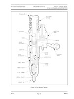
... hydraulic piston and a set of mechanical flyweights, which are driven by the engine blower shaft. Figure 28 provides an illustration of a functional diagram of a mechanical- hydraulic governor. ... fuel. Figure 28 Simplified Mechanical- Hydraulic Governor Rev. 0 ME-01 Page 35 Diesel Engine Fundamentals DOE-HDBK-1018/1-93 DIESEL ENGINE SPEED, FUEL CONTROLS, AND PROTECTION Figure 26 Fuel...
Ngày tải lên: 21/07/2014, 17:20