Mechanical Science HandbooksMechanical Science Handbooks 10000 Part 7 ppt

Mechanical Science HandbooksMechanical Science Handbooks 10000 Part 7 ppt
... Department of Energy Fundamentals Handbook MECHANICAL SCIENCE Module 2 Heat Exchangers OBJECTIVES DOE-HDBK-1018/1-93 Heat Exchangers Intentionally
Ngày tải lên: 21/07/2014, 17:20

Mechanical Science HandbooksMechanical Science Handbooks 10000 Part 9 pptx
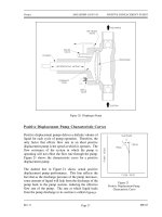
... Displacement Pump Characteristic Curves 27 Positive Displacement Pump Protection 28 Summary 28 Rev. 0 ME-03 Page i Department of Energy Fundamentals Handbook MECHANICAL SCIENCE Module 3 Pumps Heat Exchangers ... 3 Centrifugal Pump Classification by Flow 4 Multi-Stage Centrifugal Pumps 6 Centrifugal Pump Components 7 Summary 10 CENTRIFUGAL PUMP OPERATION 11 Introduction 11 Cavitation 1...
Ngày tải lên: 21/07/2014, 17:20
Mechanical Science HandbooksMechanical Science Handbooks 20000 Part 7 pps
... Corporation, 1 977 . Scheel, Gas and Air Compression Machinery, McGraw/Hill. Stewart, Harry L., Pneumatics & Hydraulics, Theodore Audel & Company. Westinghouse Technical Manual 1440-C3 07, SNUPPS, ... viii Rev. 0 OBJECTIVES DOE-HDBK-1018/2-93 Miscellaneous Mechanical Components Intentionally Left Blank ME-05 Page x Rev. 0 Miscellaneous Mechanical Components DOE-HDBK-1018/2-93 A...
Ngày tải lên: 21/07/2014, 17:20
Mechanical Science HandbooksMechanical Science Handbooks 10000 Part 13 pps
Ngày tải lên: 21/07/2014, 17:20
Mechanical Science HandbooksMechanical Science Handbooks 10000 Part 12 pot
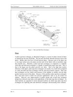
... complete assembly and the usual flow Figure 17 Two-Screw, Low-Pitch, Screw Pump Figure 18 Three-Screw, High-Pitch, Screw Pump path are shown in Figure 17. Liquid is trapped at the outer end of each ... self- priming features, it is essential that all clearances between rotating parts, and between rotating and stationary parts, be kept to a minimum in order to reduce slippage. Slippage is le...
Ngày tải lên: 21/07/2014, 17:20
Mechanical Science HandbooksMechanical Science Handbooks 10000 Part 11 doc
... DOE-HDBK-1018/1-93 Pumps Mechanical Seals In some situations, packing material is not adequate for sealing the shaft. One common alternative method for sealing the shaft is with mechanical seals. Mechanical ... in design and construction from simple pumps with relatively few parts to extremely complicated pumps with hundreds of individual parts. Some of the most common components found...
Ngày tải lên: 21/07/2014, 17:20

Mechanical Science HandbooksMechanical Science Handbooks 10000 Part 10 docx
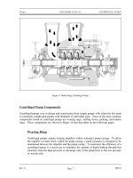
... vanes of the rotating impeller impart a radial and rotary motion to the liquid, forcing it to the outer periphery of the pump casing where it is collected in the outer part of the pump casing called ... impeller of a typical axial flow pump and the flow through a radial flow pump are shown in Figure 7. Figure 7 Axial Flow Centrifugal Pump Rev. 0 ME-03 Page 5 OBJECTIVES DOE-HDBK-1018/1-9...
Ngày tải lên: 21/07/2014, 17:20
Mechanical Science HandbooksMechanical Science Handbooks 10000 Part 8 doc
... 145°F U o = 70 BTU/hr-ft 2 -°F A o = 75 ft 2 T 2 = represents the cold fluid temperature T 2in =80°F T 2out = 120°F Counter flow ∆T lm = (200 120 o F) (145 80 o F) ln (200 120 o F) (145 80 o F) 72 o F Rev. ... for the counter flow heat exchanger yields the following result. Q 70 BTU hr ft 2 F (75 ft 2 ) (72 F) Q 3.8x10 5 BTU hr Inserting the above values...
Ngày tải lên: 21/07/2014, 17:20
Mechanical Science HandbooksMechanical Science Handbooks 10000 Part 6 pps
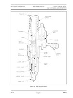
... hydraulic piston and a set of mechanical flyweights, which are driven by the engine blower shaft. Figure 28 provides an illustration of a functional diagram of a mechanical- hydraulic governor. ... in any mechanical and hydraulic governor. The Woodward speed governor operates the diesel engine fuel racks to ensure a constant engine speed is maintained at any load. The governor is a mech...
Ngày tải lên: 21/07/2014, 17:20
Mechanical Science HandbooksMechanical Science Handbooks 10000 Part 5 pps
... ~640°F and pressure 277 psia. When the piston has traveled to 3 .75 7 inches of its stroke, or the volume is again halved, the temperature climbs to 1280°F and pressure reaches 74 2 psia. With a piston ... intake Figure 17 Compression valve starts to close. At 43° ABDC (or 1 37 BTDC), the intake valve is on its seat and is fully closed. At this point the air charge is at normal pressure (14...
Ngày tải lên: 21/07/2014, 17:20