Mechanical Science HandbooksMechanical Science Handbooks 20000 Part 6 pps
Mechanical Science HandbooksMechanical Science Handbooks 20000 Part 6 pps
... Trap 36 Thermostatic Steam Traps 36 Bellows-Type Steam Trap 36 Impulse Steam Trap 37 Orifice-Type Steam Trap 38 Summary 39 ME-05 Page ii Rev. 0 Department of Energy Fundamentals Handbook MECHANICAL ... 1 Introduction 1 Reciprocating Compressors 1 Rotary Compressors 4 Centrifugal Compressors 6 Compressor Coolers 6 Hazards of Compressed Air 7 Summary 8 HYDRAULICS 10 Introduction 10 Pre...
Ngày tải lên: 21/07/2014, 17:20
Mechanical Science HandbooksMechanical Science Handbooks 20000 Part 9 pps
... 28 Miscellaneous Mechanical Components DOE-HDBK-1018/2-93 DEMINERALIZERS Figure 14 Regeneration of a Mixed-Bed Demineralizer Rev. 0 ME-05 Page 27 DEMINERALIZERS DOE-HDBK-1018/2-93 Miscellaneous Mechanical ... entrained particles. The backwash water goes out through the normal inlet distributor piping at the top of the tank, but the valves are set to direct the stream to a drain so that th...
Ngày tải lên: 21/07/2014, 17:20
Mechanical Science HandbooksMechanical Science Handbooks 20000 Part 7 pps
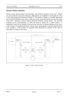
... 0 Page 6 OBJECTIVES DOE-HDBK-1018/2-93 Miscellaneous Mechanical Components TERMINAL OBJECTIVE 1.0 Without references, DESCRIBE the purpose, construction, and operation of miscellaneous mechanical ... compressor is the same force utilized by the centrifugal pump. The air particles enter the eye of the impeller, designated D in Figure 6. As the impeller rotates, air is thrown against the...
Ngày tải lên: 21/07/2014, 17:20

Mechanical Science HandbooksMechanical Science Handbooks 20000 Part 2 pps
... Valve 16 Figure 11 Angle Globe Valve 17 Figure 12 Typical Ball Valve 19 Figure 13 Plug Valve 21 Figure 14 Straight-Through Diaphragm Valve 24 Figure 15 Weir Diaphragm Valve 26 Figure 16 Variable ... FIGURES LIST OF FIGURES Figure 1 Basic Parts of a Valve 2 Figure 2 Rising Stems 4 Figure 3 Nonrising Stems 5 Figure 4 Gate Valve 9 Figure 5 Solid Wedge Gate Valve 11 Figure 6 Flexible Wedge G...
Ngày tải lên: 21/07/2014, 17:20
Mechanical Science HandbooksMechanical Science Handbooks 10000 Part 6 pps
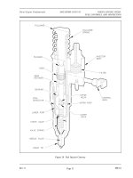
... hydraulic piston and a set of mechanical flyweights, which are driven by the engine blower shaft. Figure 28 provides an illustration of a functional diagram of a mechanical- hydraulic governor. ... fuel. Figure 28 Simplified Mechanical- Hydraulic Governor Rev. 0 ME-01 Page 35 Diesel Engine Fundamentals DOE-HDBK-1018/1-93 DIESEL ENGINE SPEED, FUEL CONTROLS, AND PROTECTION Figure 26 Fuel I...
Ngày tải lên: 21/07/2014, 17:20
Mechanical Science HandbooksMechanical Science Handbooks 20000 Part 10 ppt
... Miscellaneous Mechanical Components DOE-HDBK-1018/2-93 STEAM TRAPS Although there are several variations of the orifice-type steam trap, each has one thing in common; it contains no moving parts. One ... other in a manner that removes any particles that have collected on the metal surfaces. Some metal-edged type filters have magnets to aid in removing fine particles of magnetic materials. S...
Ngày tải lên: 21/07/2014, 17:20

Mechanical Science HandbooksMechanical Science Handbooks 20000 Part 8 potx
... piston returns to a reservoir or tank via a filter, which removes foreign particles. Rev. 0 ME-05 Page 13 Miscellaneous Mechanical Components DOE-HDBK-1018/2-93 BOILERS Summary The important information ... exert for the valve to move? Solution: Since F = P x A, then .P F A P 1848 lbf 3in. 2 P 61 6 lbf/in. 2 Hydraulic Operation The operation of a typical hydraulic system is illustra...
Ngày tải lên: 21/07/2014, 17:20
Mechanical Science HandbooksMechanical Science Handbooks 20000 Part 5 doc
... two flange faces and provide a compact, lightweight installation, particularly in larger diameter valves. ME-04 Rev.0 Page 36 Valves DOE-HDBK-1018/2-93 TYPES OF VALVES The disk lifts off of the ... for tight closure or pounded open if it is stuck shut. Gears Figure 32 Manual Gear Head If additional mechanical advantage is necessary for a manually-operated valve, the valve bonnet is fitted...
Ngày tải lên: 21/07/2014, 17:20
Mechanical Science HandbooksMechanical Science Handbooks 20000 Part 4 potx
... plug coated. Lift-type valves provide a means of mechanically lifting the tapered plug slightly to disengage it from the seating surface to permit easy rotation. The mechanical lifting can be accomplished ... the supply pressure is at least as high as the selected pressure. As illustrated in Figure 16, the principal parts of the reducing valve are the main valve; an upward-seating valve tha...
Ngày tải lên: 21/07/2014, 17:20

Mechanical Science HandbooksMechanical Science Handbooks 20000 Part 3 pdf
... DOE-HDBK-1018/2-93 VALVE FUNCTIONS AND BASIC PARTS Summary The following important information in this chapter is summarized below: Valve Functions and Basic Parts Summary There are four basic types ... halves are caused to press together under stem thrust and spread apart the disks to seal against the seats. The tapered wedges may be part of the disk halves or they may be separate element...
Ngày tải lên: 21/07/2014, 17:20