Application of the MC34063 switching regulator
Application of the MC34063 switching regulator
... 4SLVA252B–September2006–RevisedNovember2007 SubmitDocumentationFeedback www.ti.com 2FunctionalDescription FunctionalDescription Theoscillatoriscomposedofacurrentsourceandsink,whichchargeanddischargetheexternaltiming capacitor(C T )betweenanupperandlowerpresetthreshold.Thetypicalchargeanddischargecurrents are35mAand200mA,respectively,yieldingapproximatelya6:1ratio.Thus,theramp-upperiodissix ti...
Ngày tải lên: 11/04/2014, 13:12
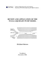
REVIEW AND APPLICATION OF THE TULSA LIQUID JET PUMP MODEL
... and therefore the fluid pressure. The smaller flow area, the higher velocity of the fluid. The static pressure of the fluid drops as the square of the velocity increase and will reach the vapour ... A. The terminology used in the model is detailed in the Nomenclature (Appendix A, page 61-62) and shown in Figure 1. The brackets on the right side of the...
Ngày tải lên: 23/10/2013, 08:42

Tài liệu Effect modification of air pollution on Urinary 8-Hydroxy-2’-Deoxyguanosine by genotypes: an application of the multiple testing procedure to identify significant SNP interactions ppt
... interactions using the bootstrap method with the combination of coefficients of the main effect and the interaction [6]. Results Table 1 shows the descriptive statistics of the demo- graphic characteristics, ... 6 of 9 result s [54-57]. None of these studies found the GSTP1 is significantly associated with the outcomes of interest although some studies found positi...
Ngày tải lên: 17/02/2014, 22:20

Tài liệu THE VALUE OF IMPROVED PUBLIC SERVICES: AN APPLICATION OF THE CHOICE EXPERIMENT METHOD TO ESTIMATE THE VALUE OF IMPROVED WASTEWATER TREATMENT INFRASTRUCTURE IN INDIA docx
... considered, and the vectors of coefficients 1 to n are attached to the vector of attributes ( Z ). The assumptions about the distribution of error terms implicit in the use of the CLM impose ... recognize the need to increase the capacity of the current STP so that all of the wastewater generated by the residents of the Municipality can be treate...
Ngày tải lên: 18/02/2014, 01:20

PHYSICS AND POLITICS OR THOUGHTS ON THE APPLICATION OF THE PRINCIPLES OF ''''NATURAL SELECTION'''' AND ''''INHERITANCE'''' TO POLITICAL SOCIETY pptx
... gives the readers of the journal the sort of words and the sort of thoughts they are used to—so, on a larger scale, the writers of an age, without thinking of it, give to the readers of the age ... nations what they are; their born structure bears the trace of the laws of their fathers;' but the ancient nations came into no such inheritance; they we...
Ngày tải lên: 06/03/2014, 13:20
APPLICATION OF THE STIRLING MODEL TO ASSESS DIVERSITY USING UIS CINEMA DATA docx
... is the market share of each statistical individual The higher the value of the index, the weaker the balance. Of course, the HHI not only depends on the balance but also on the number of ... represent only 15% of the total number of cinemas, the size of the theatres is one of the factors that explains the relatively high number of admissions pe...
Ngày tải lên: 07/03/2014, 15:20

Guide to application of the Machinery Directive 2006/42/EC potx
... (8) §385 The content of the Declaration of Incorporation Annex II 2 §386 Custody of the EC Declaration of Conformity and the Declaration of Incorporation Guide to application of the Machinery ... 13 The footnotes to the citation give the references and dates of the successive steps of the procedure. (The Position of the European Parliament of...
Ngày tải lên: 09/03/2014, 00:20

Application of the International Classification of Diseases to Dentistry and Stomatology Third Edition potx
... disorders VI. Diseases of the nervous system IX. Diseases of the circulatory system X. Diseases of the respiratory system XI. Diseases of the digestive system XII. Diseases of the skin and subcutaneous ... applicable to the superficial tissues of the tongue as well as to other soft tissue surfaces of the oral cavity. In many cases, however, there is a separat...
Ngày tải lên: 15/03/2014, 11:20
- application of the discrete wavelet transform to denoise gpr signals
- application of the theory of inventive problem solving in tunnel construction
- application of the regulations
- application of the nursing process
- application of the accounting framework
- application of the vdw eos to polymers
- application of the reporting entity concept and other amendments
- application of the regression theorem
- buying an application of the big five personality model